7.4.14 Ohms Calibration
8. After allowing sufficient settling time, set the Model 617
calibration parameter to the exact resistance value obtain-
ed for the 1COMR resistor in step 1. Again, use either the
I. Using the teraohmmeter, measure the actual resistance
calibration program or send the value over the bus.
values of the 1Gfl and 1OOMR resistors. Record these
9. Enable zero check and place the V-Q GUARD switch in
values in Table 7-6.
the OFF position. Disconnect the IOOMR resistor and
shielded &closure from the instrument. Substitute the
NOTE
Do not touch the body of these resistors to avoid
decade resistance box in its place, as shown in Figure 7-9.
contamination that could give erroneous results.
10. Select the 2OMQ range and set the decade box to the value
listed in the table.
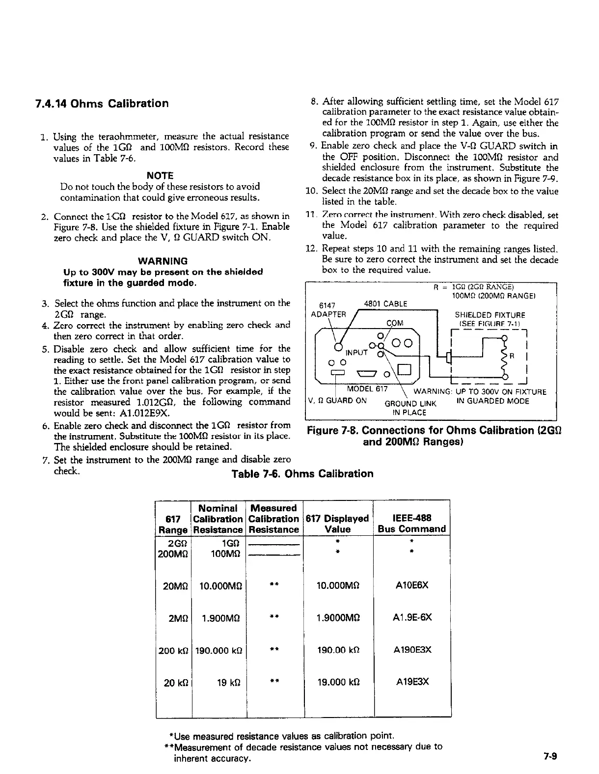
2. Connect the l,Gn resistor to the Model 617, as shown in
11. Zero correct the instrument. With zero check disabled, set
Figure 7-8. Use the shielded fiiture in Figure 7-l. Enable
the Model 617 calibration parameter to the required
zero check and place the V, n GUARD switch ON.
value.
12. Repeat steps 10 and 11 with the remaining ranges listed.
WARNING
Be sure to zero correct the instrument and set the decade
Up to 300V may be present on the shielded
fixture in the guarded mode.
box to the required value.
3. Select the ohms function and place the instrument on the
2GQ range.
4. Zero correct the instrument by enabling zero check and
then zero correct in that order.
5. Disable zero check and allow sufficient time for the
reading to settle. Set the Model 617 calibration value to
the exact resistance obtained for the 1GR resistor in step
1. Either use the front panel calibration program, or send
the calibration value over the bus. For example, if the
resistor measured 1.012GSL the following command
would be sent: A1.012E9X.
6. Enable zero check and disconnect the 1GR resistor from
the instrument. Substitute the lOOM0 resistor in its place.
The shielded enclosure should be retained.
7. Set the instrument to the 2OOMQ raw and disable zero
Figure 7-8. Connections for Ohms Calibration I2GQ
and 200MQ Ranges)
Table 7-6. Ohms Calibration
Nominal Measured
617 Calibration Calibration
Range Resistance Resistance
2GR 1GQ
200Mfl
1OOMlI
ZOMQ lO.OOOMSI l *
2MQ l.SOOMQ l *
r
6
t
17 Displayed
VailIt3
*
l
lO.OOOMO
1.9000MR
200 k0 190.000 kO l *
190.00 kR
20 kR 19 kQ l *
19.000 ka
IEEE488
lus Command
f
l
AlOE6X
Al .9E-6X
A190E3X
A19E3X
*Use measured resistance values as calibration point.
**Measurement of decade resistance values not necessary due to
inherent accuracy.
7-9