7.4.12 Coulombs Calibration
Use the following procedure to calibrate the 20nC range.
Once this range is calibrated, the two remaining ranges are
automatically calibrated.
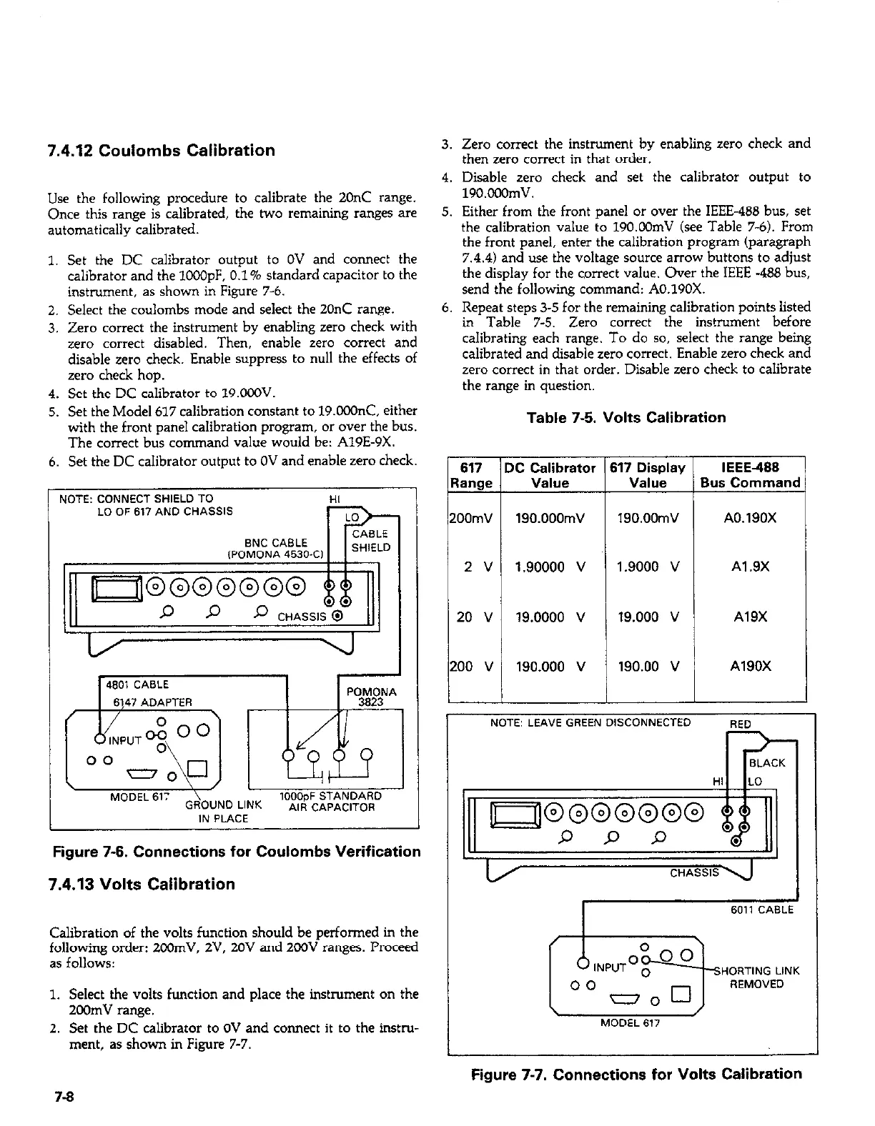
1. Set the DC calibrator output to OV and connect the
calibrator and the 1CCOpF. 0.1% standard capacitor to the
instrument, as shown in Figure 7-6.
2. Select the coulombs mode and select the 2OnC range.
3. Zero correct the instrument by enabling zero check with
zero correct disabled. Then, enable zero correct and
disable zero check. Enable suppress to null the effects of
zero check hop.
4. Set the DC calibrator to 19.ooOV.
5. Set the Model 617 calibration constant to 19.OOOnC. either
with the front panel calibration program, or over the bus.
The correct bus command value would be: A19E-9X.
6. Set the DC calibrator output to OV and enable zero check.
I UOTE: CONNECT SHIELD TO
HI
LO OF 617 AND CHASSIS
BNC CABLE
,POMDNA 4630-C,
SHIELD
4601 CABLE
1 1
6147 ADAPTFR
\
\ ,
I
I
MODEL 61:
GR\OUNO LINK
,OO&,F STANDARD
AIR CAPACITOR
IN PLACE
Figure 7-6. Connections for Coulombs Verification
7.4.13 Volts Calibration
Calibration of the volts f?mction should be performed in the
following order: 2COrnV. 2V. 20V and 200V ranges. Proceed
as follows:
1. Select the volts function and place the instrument on the
2Gibnv range.
2. Set the DC calibrator to OV and connect it to the instru-
ment, as shown in Figure 7-7.
3. Zero correct the instrument by enabling zero check and
then zero correct in that order.
4. Disable zero check and set the calibrator output to
190.000mV.
5. Either from the front panel or over the IEEE-466 bus, set
the calibration value to 190.00mV (see Table 7-6). From
the front panel, enter the calibration program (paragraph
7.4.4) and use the voltage source arrow buttons to adjust
the display for the correct value. Over the IEEE -488 bus,
send the following command: AO.19OX.
6. Repeat steps 3-5 for the remaining calibration points listed
in Table 7-5. Zero correct the instrument before
calibrating each range. To do so, select the range being
calibrated and disable zero correct. Enable zero check and
zero correct in that order. Disable zero check to calibrate
the range in question.
Table 7-5. Volts Calibration
617 DC Calibrator 617 Display IEEE488
Range
Value
Value Bus Command
200mV
190.000mV 190.00mV
A0.190X
2V
1.90000 v
1.9000 v Al .9X
20 v
19.0000 v
19.000 v A19X
200 v
190.000 v
190.00 v A190X
NOTE: LEAVE GREEN DISCONNECTED
RED
7-9
Figure 7-7. Connections for Volts Calibration