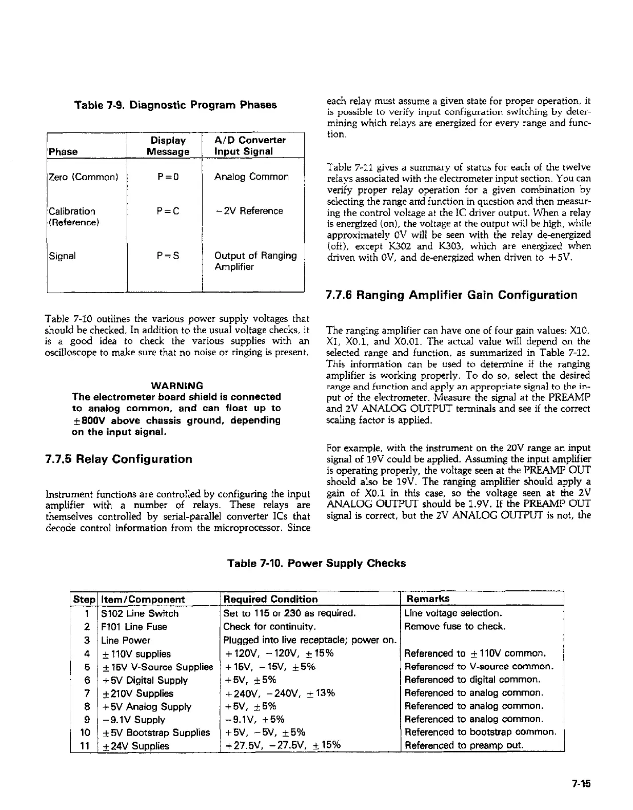
Table 7-9. Diagnostic Program Phases
Zero ICommon)
T
Display
Message
P=O
P=C
P=S
AID Converter
input Signal
Analog Common
- 2v Reference
Output of Ranging
Amplifier
Table 7-10 outlines the various power supply voltages that
should be checked. In addition to the usual voltage checks, it
is a good idea to check the various supplies with an
oscilloscope to make sure that no noise or ringing is present.
WARNING
The electrometer board shield is connected
to analog common, and can float up to
+9OOV above chassis ground, depending
on the input signal.
7.7.5 Relay Configuration
Instrument functions are controlled by configuring the input
amplifier with a number of relays. These relays are
themselves controlled by serial-parallel converter 1Cs that
decode control information from the microprocessor. Since
L
each relay must assume a given state for proper operation. it
is possible to verify input configuration switching by deter-
mining which relays are energized for every range and func-
tion.
Table 7-11 gives a summary of status for each of the twelve
relays associated with the electrometer input section. You can
verify proper relay operation for a given combination by
selecting the range and function in question and then measur-
ing the control voltage at the lC driver output. When a relay
is energized (on), the voltage at the output will be high, while
approximately OV will be seen with the relay de-energized
(off), except K302 and K303, which are energized when
driven with OV, and de-energized when driven to +5V.
7.7.5 Ranging Amplifier Gain Configuration
The ranging amplifier can have one of four gain values: X10,
Xl, X0.1, and X0.01. The actual value will depend on the
selected range and function, as summarized in Table 7-12.
This information can be used to determine if the ranging
amplifier is working properly. To do so, select the desired
range and function and apply an appropriate signal to the in-
put of the electrometer. .Measure the signal at the PREAMP
and 2V ANALOG OUTPUT terminals and see if the correct
scaling factor is applied.
For example, with the instrument on the 20V range an input For example, with the instrument on the 20V range an input
signal of 19V could be applied. Assuming the input amplifier signal of 19V could be applied. Assuming the input amplifier
is operating properly, the voltage seen at the PREAMP OUT is operating properly, the voltage seen at the PREAMP OUT
should also be 19V. The ranging amplifier should apply a should also be 19V. The ranging amplifier should apply a
gain of X0.1 in this case, so the voltage seen at the 2V gain of X0.1 in this case, so the voltage seen at the 2V
ANALOG OUTPUT should be 1.9V. If the PREAMP OUT ANALOG OUTPUT should be 1.9V. If the PREAMP OUT
signal is correct, but the ZV ANALOG OUTPUT is not, the signal is correct, but the ZV ANALOG OUTPUT is not, the
Table 7-10. Power Supply Checks
Step Item/Component
Required Condition
1 S102 Line Switch
Set to 115 or 230 as required.
2 FlOl Line Fuse
Check for continuity.
3 Line Power
Plugged into live receptacle; power on
4 f 1lOV supplies
+12ov, -12ov. +15%
5 f 15V V-Source Supplies
+ 15V, - 15V, *5%
6 + 5V Digital Supply
+5v, $5%
7 +21OV Supplies +24OV, -24OV, + 13%
8 + 5V Analog Supply
+5v, +5%
9 -9.lV Supply
-9.lV, +5%
10 *SV Bootstrap Supplies
+5v, -5v, *5%
11 +24V Supplies
+27.!iV. -27.5V. i: 15%
Remarks
Line voltage selection.
Remove fuse to check.
Referenced to + 11OV common.
Referenced to V-source common.
Referenced to digital common.
Referenced to analog common.
Referenced to analog common.
Referenced to analog common.
Referenced to bootstrap common.
Referenced to preamp out.
7-15