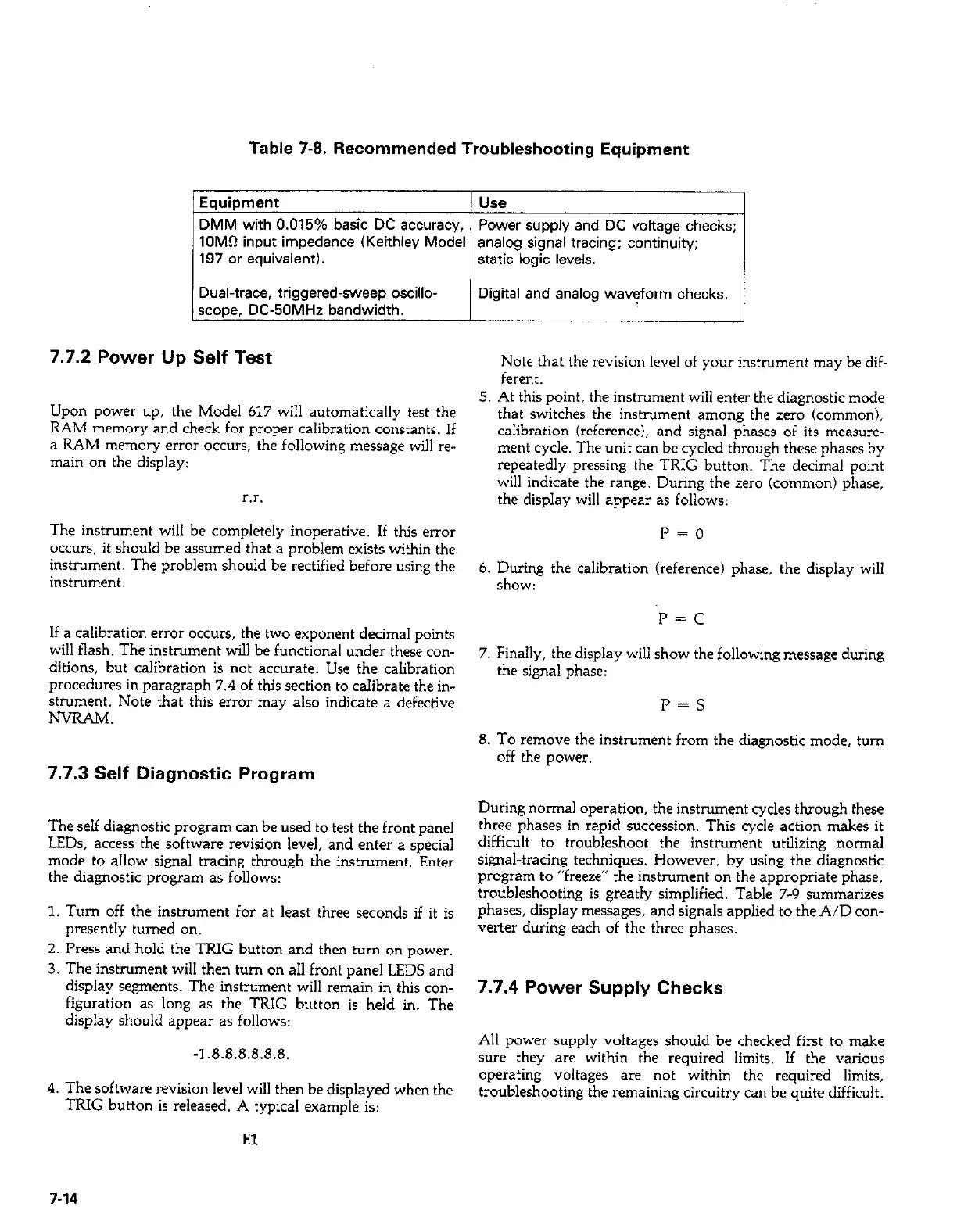
Table 7-8. Recommended Troubleshooting Equipment
Equipment
/ use
DMM with 0.015% basic DC accuracy, 1 Power supply and DC voltage checks;
1OMD input impedance (Keithley Modal analog signal tracing; continuity;
197 or equivalent).
static logic levels.
Dual-trace, triggered-sweep oscillo-
scooa. DC-5OMHz bandwidth.
Digital and analog waveform checks.
7.7.2 Power Up Self Test
5
Upon power up, the Model 617 will automatically test the
RAM memory and check for proper calibration constants. If
a RAM memory error occurs, the following message will re-
main on the display:
r.r.
The instrument will be completely inoperative. If this error
occurs, it should be assumed that a problem exists within the
instrument. The problem should be rectified before using the
6
instrument.
If a calibration error occurs, the two exponent decimal points
will flash. The instrument will be functional under these con-
7
ditions, but calibration is not accurate. Use the calibration
procedures in paragraph 7.4 of this section to calibrate the in-
strument. Note that this error may also indicate a defective
NVRAM.
7.7.3 Self Diagnostic Program
8
Note that the revision level of your instrument may be dif-
ferent.
At this point, the instrument will enter the diagnostic mode
that switches the instrument among the zero (common),
calibration (reference), and signal phases of its measure-
ment cycle. The unit can be cycled through these phases by
repeatedly pressing the TRIG button. The decimal point
will indicate the range. During the zero (common) phase,
the display will appear as follows:
r=o
During the calibration (reference) phase, the display will
show:
P=C
Finally, the display will show the following message during
the signal phase:
P=S
To remove the instrument from the diagnostic mode, turn
off the power.
The self diagnostic program can be used to test the front panel
LEDs, access the software revision level, and enter a special
mode to allow signal tracing through the instrument. Enter
the diagnostic program as follows:
1. Turn off the instrument for at least three seconds if it is
presently turned on.
2. Press and hold the TRIG button and then turn on power.
3. The instrument will then turn on all front panel LEDS and
display segments. The instrument will remain in this con-
figuration as long as the TRIG button is held in. The
display should appear as follows:
-1.8.8.8.8.8.8.
4. The software revision level will then be displayed when the
TRIG button is released. A typical example is:
During normal operation, the instrument cycles through these
three phases in rapid succession. This cycle action makes it
difficult to troubleshoot the instrument utilizing normal
signal-tracing techniques. However, by using the diagnostic
program to “freeze” the instrument on the appropriate phase,
troubleshooting is greatly simplified. Table 7-9 summarizes
phases, display messages, and signals applied to the A/D con-
verter during each of the three phases.
7.7.4 Power Supply Checks
All power supply voltages should be checked first to make
sure they are within the required limits. If the various
operating voltages are not within the required limits,
troubleshooting the remaining circuitry can be quite difficult.
El
7-14