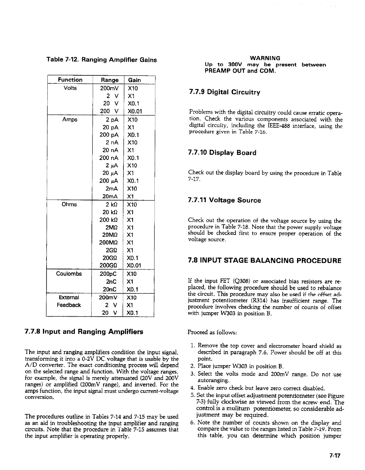
Table 7-12. Ranging Amplifier Gains
Function
Volts
AmDs
t
Ohms
I--
Coulombs
7.7.8 Input and Ranging Amplifiers
Range
200mV
2 v
20 v
200 v
2 PA
20 pA
200 pA
2 nA
20 nA
200 nA
2/rA
20 pA
200 pA
2mA
20mA
2 kil
20 kQ
200 kR
2MiI
20MR
200MR
2GQ
20GQ
200Gfl
2oopc
2nC
20nC
200mV
2 v
20 v
Gain
x10
Xl
x0.1
x0.01
x10
Xl
x0.1
x10
Xl
x0.1
x10
Xl
x0.1
x10
Xl
x10
Xl
Xl
Xl
Xl
Xl
Xl
x0.1
x0.01
x10
Xl
x0.1
x10
Xl
x0.1
cl
i
i
The input and ranging amplifiers condition the input signal,
transforming it into a O-ZV DC voltage that is usable by the
A/D converter. The exact conditioning process will depend
on the selected range and function. With the voltage ranges,
for example, the signal is merely attenuated (ZOV and 2oOV
ranges) or amplified (2oOmV range), and inverted. For the
amps function, the input signal must undergo current-voltage
conversion.
The procedures outline in Tables 7-14 and 7-15 may be used
as an aid in troubleshooting the input amplifier and ranging
circuits. Note that the procedure in Table 7-15 assumes that
the input amplifier is operating properly.
WARNING
Up to 300V may be present between
PREAMP OUT and COM.
7.7.9 Digital Circuitry
Problems with the digital circuitry could cause erratic opera-
tion. Check the various components associated with the
digital circuity, including the IEEE-488 interface, using the
procedure given in Table 7-16.
7.7.10 Display Board
Check out the display board by using the procedure in Table
7-17.
7.7.11 Voltage Source
Check out the operation of the voltage source by using the
procedure in Table 7-l&Note that the power supply voltage
should be checked first to ensure proper operation of the
voltage source.
7.8 INPUT STAGE BALANCING PROCEDURE
If the input FET (Q308) or associated bias resistors are re-
placed, the following procedure should be used to rebalance
the circuit. This procedure may also be used if the offset ad-
justment potentiometer (R314) has insufficient range. The
procedure involves checking the number of couILts of offset
with jumper W303 in position B.
Proceed as follows:
1. Remove the top cover and electrometer board shield as
described in paragraph 7.6. Power should be off at this
point.
2. Place jumper W303 in position 8.
3. Select the volts mode and 200mV range. Do not use
autoranging.
4. Enable zero check but leave zero correct disabled.
5. Set the input offset adjustment potentiometer (see Figure
7-3) fully clockwise as viewed from the screw end. The
control is a m&turn potentiometer, so considerable ad-
justment may be required.
6. Note the number of counts shown on the display and
compare the value to the ranges listed in Table 7-19. From
this table, you can determine which position jumper
7-17