W303 should be placed in. For example, if the display
shows between -1200 and +200 counts. jumper W303
should be placed in position C.
7. Place the jumper in accordance with the results of step 6.
8. Replace the electrometer board shield.
9. Turn on the power and allow the instrument to warm up
for one hour before performing the following adjustment.
10. Set the input offset potentiometer (R314) for a reading of
00.00 +1 count on the display.
11. Replace the top cover when the procedure is complete.
7.9 HANDLING AND CLEANING
PRECAUTIONS
When troubleshooting or othenvise working inside the instrw
mat, care should be taken not to indiscriminately touch PC
board traces and open wires to avoid contaminating them
with body oils or other foreign matter. In particular, there are
two areas within the Model 617 that have numerow high im-
pedance nodes where contamination could cause degraded
performance. These include the input amplifier area on the
eiectrometer board and the ranging amplifier section location
on the mother board.
The same general precautions apply when replacing parts in
these areas. When unsoldering and soldering parts, be careful
not to spread the flux around the board to adjacent areas.
After replacing parts, or if contamination is suspected, use the
following procedure to clean the affected area.
1. Using a squeeze bottle, carefully apply clean, uncon-
taminated methanol to the area to be cleaned. Use suffi-
cient solution to throughly wet the circuit board.
2. Using a small, cleati brush, wipe the area thoroughly until
it is free of flux or contaminants. In some cases, it may be
helpful to tilt the board at an angle and brush con-
taminants away from the affected area, allowing con-
taminated residue and methanol to run off the board.
3. Wash the area again with fresh, clean methanol.
4. Once the area is thoroughly cleaned, is should be dryed
with pressurized dry, clean air or nitrogen. Do not use
compressed air from an ordinary air compressor, as oil
particles in the air could contaminate the circuit board.
5. After cleaning or parts replacement check to see that any
components connected to the Teflon insulators are not
physically touching the board or adjacent parts.
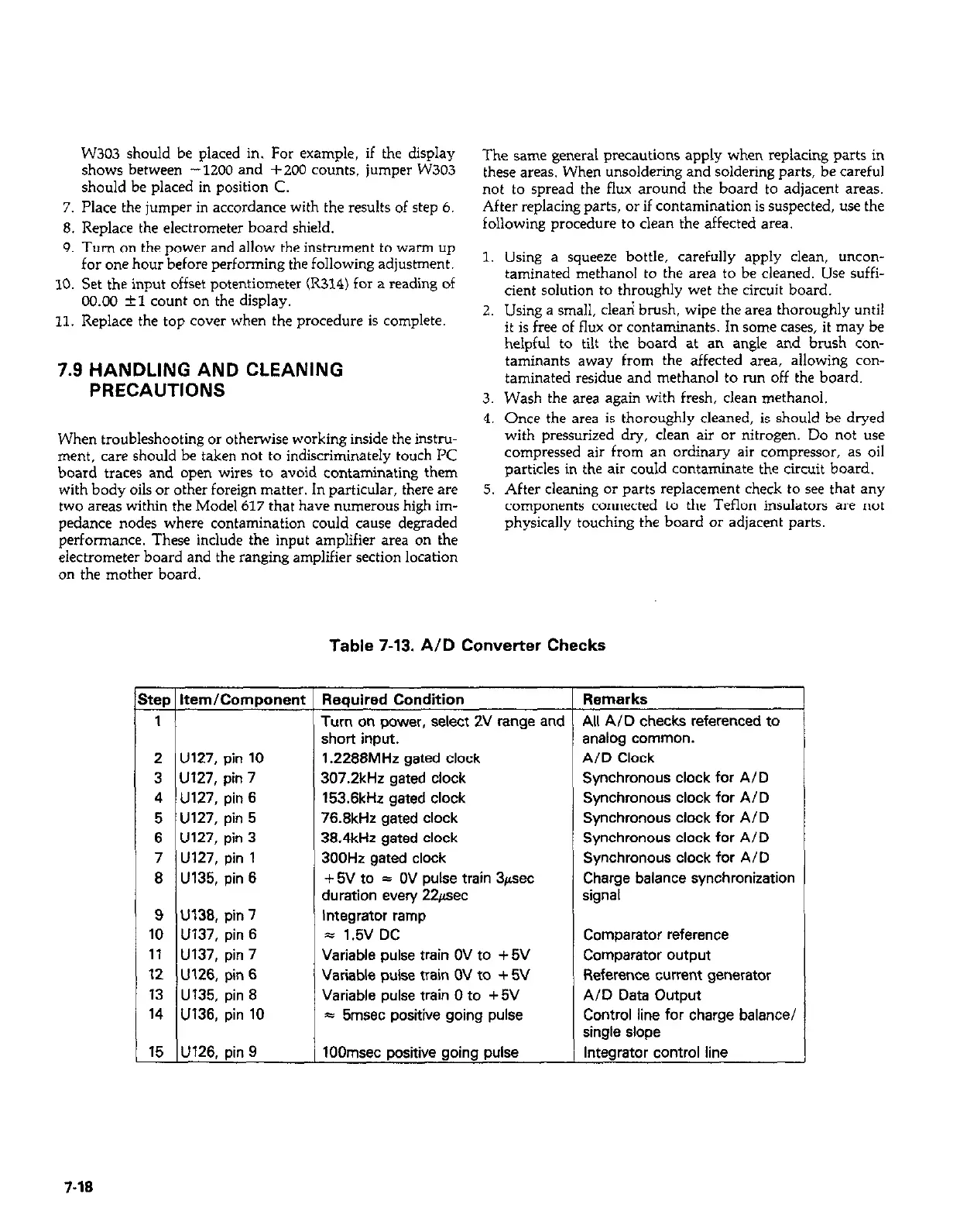
Table 7-13. AID Converter Checks
2 U127, pin 10
3 Ul27, pin 7
4 U127, pin 6
5 U127, pin 5
6 U127, pin 3
7 U127, pin 1
8 U135, pin 6
9 U138, pin 7
10 U137, pin 6
11 U137, pin 7
12 U126, pin 6
13 U135, pin 8
14 U136, pin 10
15 U126, pin 9
Required Condition
Turn on power, select 2V range and
short input.
1.2288MHz gated clock
307.2kHz sated clock
153.8kHz gated clock
76.8kHz gated clock
38.4kHz gated clock
300Hz gated clock
+ 5V to = OV pulse train 3/rsec
duration every 22eec
Integrator ramp
5 1.5V DC
Variable pulse train OV to +5V
Variable pulse train OV to + 5V
Variable pulse train 0 to + 5V
= 5msec positive going pulse
1OOmsec positive going pulse
f
Remarks
All AID checks referenced to
analog common.
AID Clock
Synchronous clock for A/D
Synchronous clock for A/D
Synchronous clock for A/D
Synchronous clock for AID
Synchronous clock for A/D
Charge balance synchronization
signal
Comparator reference
Comparator output
Reference current generator
A/D Data Output
Control line for charge balance/
single slope
Integrator control line
7-18