Performance Verification
1-13
2GΩ-200GΩ range verification
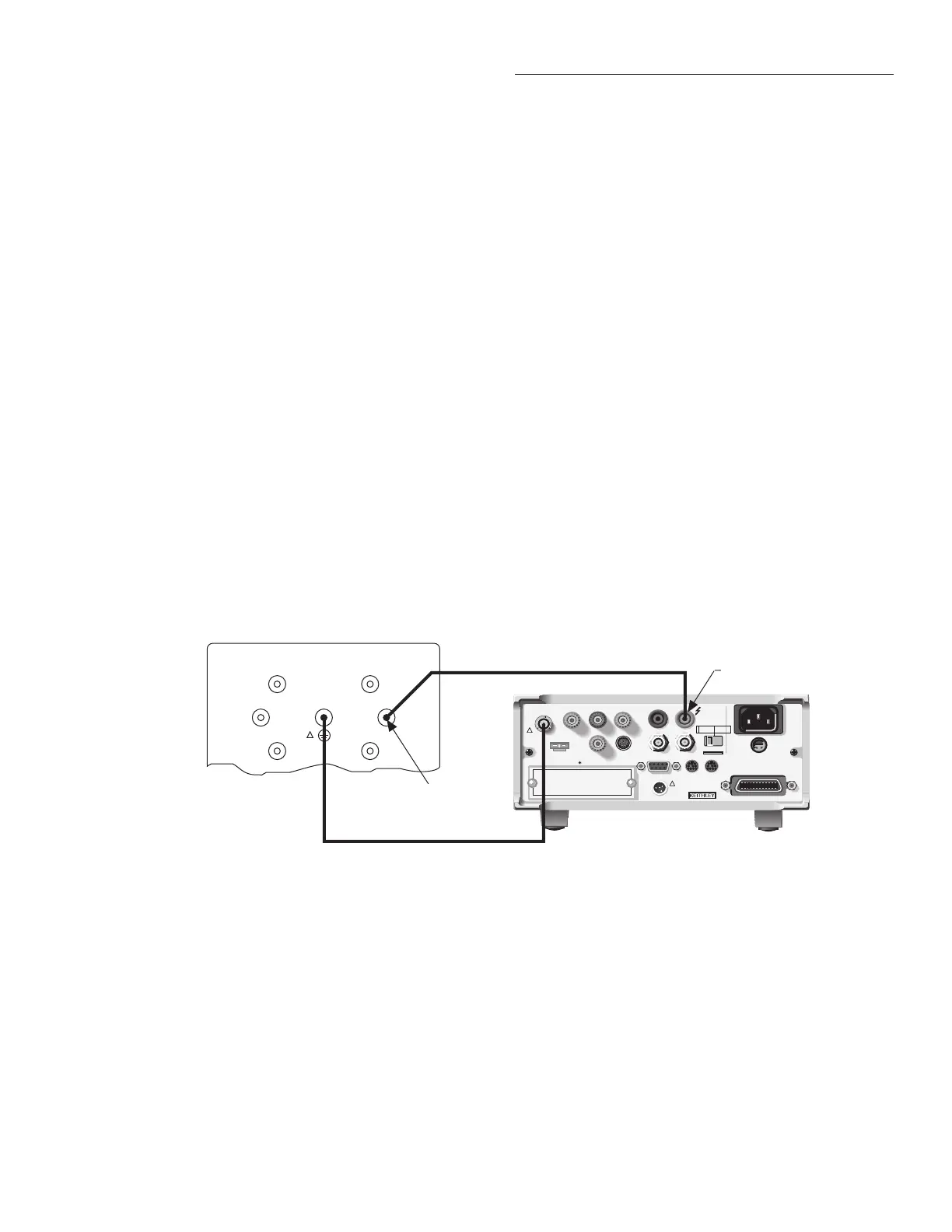
1. Connect the nominal 1GΩ characterized resistor from
the Model 5156 Calibration Standard to the Model
6517A. (See Figure 1-6.)
2. Select the ohms function.
3. Place the voltage source in operate.
4. Select the 2GΩ range on the Model 6517A.
5. Make sure that zero check is disabled, and allow the
reading to settle.
6. Verify that the displayed reading is within the calculated
reading limits listed in Table 1-9.
7. Repeat steps 4 through 6 for the 20GΩ and 200GΩ
ranges.
8. Turn off the voltage source, then disconnect the calibra-
tion standard from the Model 6517A.
2TΩ-200TΩ range verification
1. Connect the nominal 1TΩ characterized resistor to the
Model 6517A. (See Figure 1-7.)
NOTE
Standard resistors must be characterized
to an uncertainty at least four times better
than the equivalent Model 6517A accu-
racy specifications. These resistors must
be mounted in specially shielded test fix-
tures to minimize noise. (See Figure 1-8
for details on test fixture construction.)
WARNING
Hazardous voltage (400V) will be used
in the following steps. Do not touch con-
necting cables or test leads while the
voltage source is in operate.
2. Select the 2TΩ range on the Model 6517A.
3. Place the voltage source in operate.
4. Make sure that zero check is disabled, and allow the
reading to settle.
5. Verify that the displayed reading is within the calculated
limits listed in Table 1-9.
6. Repeat steps 2 through 5 for the 20TΩ and 200TΩ
ranges.
7. Turn off the voltage source, then disconnect the standard
resistor from the Model 6517A.
Figure 1-6
Connections for ohms verification (2G
Ω
–200G
Ω
ranges)
100GΩ
1nF
100nF
10GΩ
1GΩ
100MΩ
WARNING:
NO INTERNAL OPERATOR SERVICABLE PARTS,SERVICE BY QUALIFIED PERSONNEL ONLY.
WARNING:
NO INTERNAL OPERATOR SERVICABLE PARTS,SERVICE BY QUALIFIED PERSONNEL ONLY.
CAUTION:
FOR CONTINUED PROTECTION AGAINST FIRE HAZARD,REPLACE FUSE WITH SAME TYPE AND RATING.
CAUTION:
FOR CONTINUED PROTECTION AGAINST FIRE HAZARD,REPLACE FUSE WITH SAME TYPE AND RATING.
INPUT
250V PEAK
!
LINE RATING
50-60HZ
50VA MAX
AC ONLY
LINE FUSE
SLOWBLOW
1/2A 90-125V
1/4A 180-250V
IEEE-488
(CHANGE IEEE ADDRESS
WITH FRONT PANEL MENU)
DIGITAL
I/O
TRIG LINK
115V
LO
HI
RS232
!
MADE
IN
U.S.A.
PREAMP OUT
250 PEAK
COMMON 2V ANALOG
OUTPUT
TEMP
TYPE K
HUMIDITY
OPTION SLOT
V SOURCE
EXT TRIG
IN
MTR COMP
OUT
INTERLOCK
SELECTED
LINE VOLTAGE
90-110V
105-125V
180-220V
210-250V
1010V
PEAK
750V
PEAK
Triax Cable
Model 6517 Electrometer
Connect to
Center Conductor
Model 5156 Electrometer Calibration Standard
OUTPUT
Voltage Source HI
!
Note: Be sure shield and
Chassis are linked.