Calibration
2-11
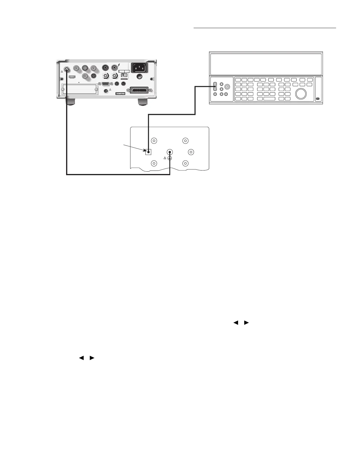
Step 5: Coulombs Calibration
1. Connect the calibration standard and DC voltage cali-
brator to the Model 6517A INPUT jack, as shown in
Figure 2-5. Initially, make connections to the 1nF capac-
itor in the standards box.
2. Set the output voltage of the DC calibrator to 0.00000V.
3. Press the ENTER key to begin zero check A calibration.
During this step, the instrument will display:
Performing 2nC zero check A cal
4. After zero cal, the instrument will display the following:
CONNECT 2V to 1000pF
ENTER to continue; EXIT to abort
5. Press the ENTER key, and note that the instrument dis-
plays the actual calibration value:
+1.9000000 V
Use ▲, ▼, , ,ENTER,EXIT or INFO
6. Set the DC calibrator voltage to +1.9000000V DC. If
necessary, set the displayed calibration value to agree
with the actual calibrator voltage, then press the ENTER
key. During this step, the instrument will display the
following:
Performing 2 nC cal
Figure 2-5
Connections for coulombs calibration
WARNING:
NO INTERNAL OPERATOR SERVICABLE PARTS,SERVICE BY QUALIFIED PERSONNEL ONLY.
WARNING:
NO INTERNAL OPERATOR SERVICABLE PARTS,SERVICE BY QUALIFIED PERSONNEL ONLY.
CAUTION:
FOR CONTINUED PROTECTION AGAINST FIRE HAZARD,REPLACE FUSE WITH SAME TYPE AND RATING.
CAUTION:
FOR CONTINUED PROTECTION AGAINST FIRE HAZARD,REPLACE FUSE WITH SAME TYPE AND RATING.
INPUT
250V PEAK
!
LINE RATING
50-60HZ
50VA MAX
AC ONLY
LINE FUSE
SLOWBLOW
1/2A 90-125V
1/4A 180-250V
IEEE-488
(CHANGE IEEE ADDRESS
WITH FRONT PANEL MENU)
DIGITAL
I/O
TRIG LINK
115V
LO
HI
RS232
!
MADE
IN
U.S.A.
PREAMP OUT
250 PEAK
COMMON 2V ANALOG
OUTPUT
TEMP
TYPE K
HUMIDITY
OPTION SLOT
V SOURCE
EXT TRIG
IN
MTR COMP
OUT
INTERLOCK
SELECTED
LINE VOLTAGE
90-110V
105-125V
180-220V
210-250V
1010V
PEAK
750V
PEAK
Low-noise
Coax Cable
Model 6517 Electrometer
Connect Cable
Shield to
Output LO
DC Voltage Calibrator
Note: Connect voltage calibrator
to appropriate capacitor.
Be sure shield to chassis
link is connected. (See Text)
Triax Cable
100GΩ
1nF
100nF
10GΩ
1GΩ
100MΩ
Model 5156 Electrometer Calibration Standard
OUTPUT
Charge Filter
!
7. Set the calibrator output to 0V, then press the ENTER
key to automatically perform 2nC zero check B
calibration.
8. After zero check calibration, the instrument will prompt
you for the next calibration step:
CONNECT -2V to 1000p
ENTER to continue; EXIT to abort
9. Set the DC voltage calibrator to -1.900000V, and allow
sufficient time for settling.
10. Press the ENTER key, and note that the instrument dis-
plays the exact calibration value:
-1.9000000 V
Use ▲, ▼, , ,ENTER,EXIT or INFO
11. If necessary, adjust the display to agree with the exact
calibration value.
12. Press the Model 6517A ENTER key. During this cali-
bration phase, the instrument will display the following:
Performing -2nC cal
13. Repeat steps 4 through 12 for the remaining coulombs
ranges using the voltage values and capacitance stan-
dards values summarized in Table 2-6.