Calibration
2-9
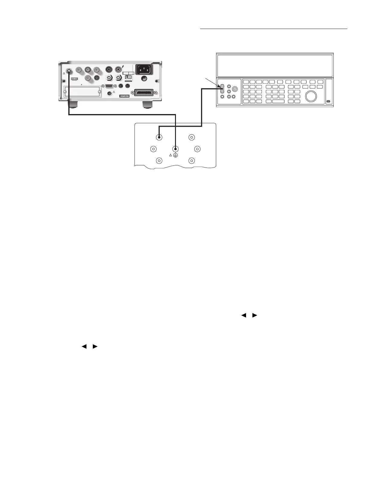
4. Connect the Model 5156 Electrometer Calibration Stan-
dard and the DC voltage calibrator to the Model 6517A
INPUT jack, as shown in Figure 2-3. Initially, make
connections to the 100G
Ω
resistance in the standards
box.
5. After the zero current calibration step, the instrument
will prompt you as follows:
CONNECT 2V to 100G
ENTER to continue; EXIT to abort
6. Set the DC voltage calibrator to exactly 1.900000V DC.
Make sure the 100G
Ω
resistor in the calibration stan-
dard is connected, then press the Model 6517A ENTER
key. The instrument will prompt for the exact calibration
value:
1.9000000 V
Use
▲
,
▼
, , ,ENTER,EXIT or INFO
NOTE
For all calibration steps that involve the
Model 5156, you can set calibration values
in either one of two ways: (1) set the cali-
brator output to agree with the displayed
value, or (2) adjust the display to agree
with the calibrator value.
Figure 2-3
Connections for 20pA–2µA range calibration
WARNING:
NO INTERNAL OPERATOR SERVICABLE PARTS,SERVICE BY QUALIFIED PERSONNEL ONLY.
WARNING:
NO INTERNAL OPERATOR SERVICABLE PARTS,SERVICE BY QUALIFIED PERSONNEL ONLY.
CAUTION:
FOR CONTINUED PROTECTION AGAINST FIRE HAZARD,REPLACE FUSE WITH SAME TYPE AND RATING.
CAUTION:
FOR CONTINUED PROTECTION AGAINST FIRE HAZARD,REPLACE FUSE WITH SAME TYPE AND RATING.
INPUT
250V PEAK
!
LINE RATING
50-60HZ
50VA MAX
AC ONLY
LINE FUSE
SLOWBLOW
1/2A 90-125V
1/4A 180-250V
IEEE-488
(CHANGE IEEE ADDRESS
WITH FRONT PANEL MENU)
DIGITAL
I/O
TRIG LINK
115V
LO
HI
RS232
!
MADE
IN
U.S.A.
PREAMP OUT
250 PEAK
COMMON 2V ANALOG
OUTPUT
TEMP
TYPE K
HUMIDITY
OPTION SLOT
V SOURCE
EXT TRIG
IN
MTR COMP
OUT
INTERLOCK
SELECTED
LINE VOLTAGE
90-110V
105-125V
180-220V
210-250V
1010V
PEAK
750V
PEAK
Low-noise
Coax Cable
Triax Cable
Model 6517 Electrometer
Connect Cable
Shield to
Output LO
BNC-to-dual
Banana Plug
Adapter
DC Voltage Calibrator
Note: Connect Calibrator to
Appropriate Resistor.
Link Chassis and Shield
(See Text)
100GΩ
1nF
100nF
10GΩ
1GΩ
100MΩ
Model 5156 Electrometer Calibration Standard
OUTPUT
!
7. Adjust the calibrator voltage to agree with the exact dis-
play value, then press the ENTER key. During this step,
the instrument will display the following:
Performing 20 pA cal
8. Next, the instrument will prompt you as follows:
CONNECT -2V to 100G
ENTER to continue; EXIT to abort
9. Press the Model 6517A ENTER key. The instrument
will prompt for the exact calibration value:
-1.9000000 V
Use ▲, ▼, , ,ENTER,EXIT or INFO
10. Set the calibrator output to the display value, then press
the ENTER key. The unit will display the following dur-
ing this calibration step:
Performing -20 pA Calibration
11. Repeat steps 5 through 10 for the 200pA through 2µA
ranges using the voltages and resistance standards sum-
marized in Table 2-4.
12. Disconnect the calibration standard and voltage calibra-
tor from the instrument, and connect the DC current cal-
ibrator directly to the Model 6517A INPUT jack (see
Figure 2-4).
13. At this point, the Model 6517A will display the
following:
CONNECT 19.00000 µA
ENTER to continue; EXIT to abort