Performance Verification
1-16
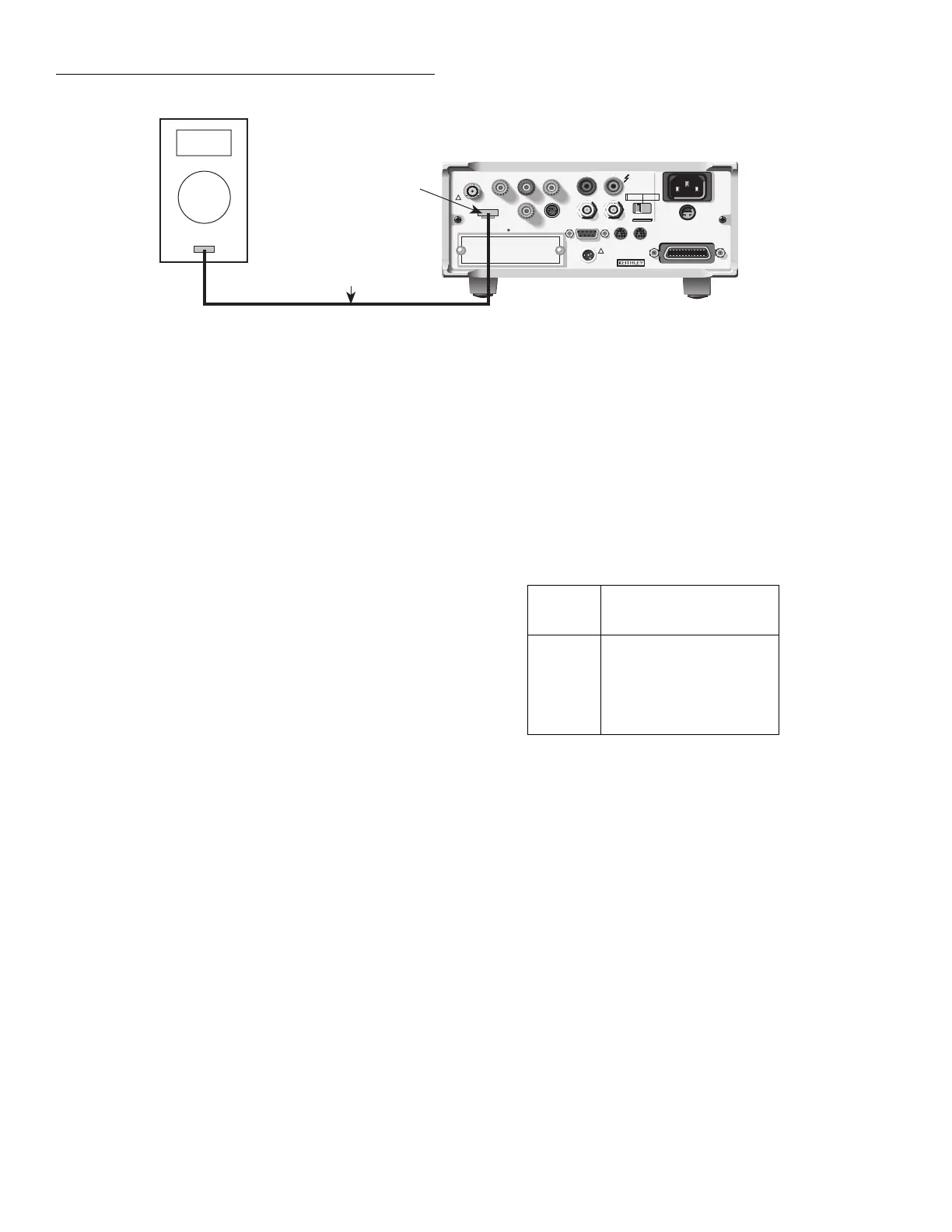
1.12 Humidity verification
Humidity measurement accuracy is checked by applying an
accurate 0-1V DC voltage to the Model 6517A and verifying
that the humidity readings are within specified limits.
Proceed as follows:
1. With the power off, connect the DC calibrator to the
Model 6517A HUMIDITY connector, as shown in Fig-
ure 1-11. Use short lengths of solid #22AWG copper
wire and alligator clips to make the connections, and be
sure to observe proper polarity (calibrator HI to HU-
MIDITY +V and calibrator LO to HUMIDITY -V).
2. Turn on the power to the Model 6517A and the calibra-
tor, and allow a one-hour warm-up period before mak-
ing measurements.
3. Select the Model 6517A humidity display with DIS-
PLAY PREV key.
4. Set the DC calibrator output to +0.2500V.
CAUTION
Do not exceed +2V input to the
HUMIDITY jack, and be sure to
observe proper polarity. Failure to do so
may result in damage to the unit.
WARNING:
NO INTERNAL OPERATOR SERVICABLE PARTS,SERVICE BY QUALIFIED PERSONNEL ONLY.
WARNING:
NO INTERNAL OPERATOR SERVICABLE PARTS,SERVICE BY QUALIFIED PERSONNEL ONLY.
CAUTION:
FOR CONTINUED PROTECTION AGAINST FIRE HAZARD,REPLACE FUSE WITH SAME TYPE AND RATING.
CAUTION:
FOR CONTINUED PROTECTION AGAINST FIRE HAZARD,REPLACE FUSE WITH SAME TYPE AND RATING.
INPUT
250V PEAK
!
LINE RATING
50-60HZ
50VA MAX
AC ONLY
LINE FUSE
SLOWBLOW
1/2A 90-125V
1/4A 180-250V
IEEE-488
(CHANGE IEEE ADDRESS
WITH FRONT PANEL MENU)
DIGITAL
I/O
TRIG LINK
115V
LO
HI
RS232
!
MADE
IN
U.S.A.
PREAMP OUT
250 PEAK
COMMON 2V ANALOG
OUTPUT
TEMP
TYPE K
HUMIDITY
OPTION SLOT
V SOURCE
EXT TRIG
IN
MTR COMP
OUT
INTERLOCK
SELECTED
LINE VOLTAGE
90-110V
105-125V
180-220V
210-250V
1010V
PEAK
750V
PEAK
EXT Temp
Jack
Type K
Thermocouple Wire
Model 6517 Electrometer
Type K
Thermocouple Simulator/Calibrator
Figure 1-10
Connections for temperature verification
5. Allow the reading to settle, then verify that the Model
6517A humidity reading is within the limits summa-
rized in Table 1-12.
6. Repeat steps 4 and 5 for each of the voltage/humidity
reading combinations summarized in Table 1-12.
Table 1-12
Limits for humidity verification
Applied
voltage
Humidity reading limits
(1 year, 18° to 28°C)
0.0000V
0.2500V
0.5000V
0.7500V
1.0000V
0% to 1%
24% to 26%
49% to 51%
74% to 76%
99% to 101%