Calibration
2-10
14. Press the Model 6517A ENTER key. The unit will
prompt for the exact calibration value:
19.000000 µA
Use ▲, ▼, , ,ENTER,EXIT, or INFO
15. Set the calibrator output to exactly +19.000000µA DC,
make certain that the displayed value agrees with the
applied current, then press the ENTER key. During this
calibration phase, the unit will display the following:
Performing 20 µA cal
Table 2-4
Amps calibration summary (20pA–2µA ranges)
6517A
range
Calibrator
voltage
Resistance
1
standard
Nominal
2
current
—
20pA
20pA
200pA
200pA
2nA
2nA
20nA
20nA
200nA
200nA
2µA
2µA
0.00000V
1.900000V
-1.900000V
1.900000V
-1.900000V
1.900000V
-1.900000V
1.900000V
-1.900000V
19.00000V
-19.00000V
190.0000V
-190.0000V
100GΩ
100GΩ
100GΩ
10GΩ
10GΩ
1GΩ
1GΩ
100MΩ
100MΩ
100MΩ
100MΩ
100MΩ
100MΩ
0pA
19pA
-19pA
190pA
-190pA
1.9nA
-1.9nA
19nA
-19nA
190nA
-190nA
1.9µA
-1.9µA
1
Actual resistance standard value determined from calibration data sup-
plied with standard.
2
Actual calibration current : I = V/R, where is the calibration voltage,
and R is the actual resistance standard value. When using the Model
5156 Electrometer Calibration Standard, the Model 6517A automati-
cally calculates the actual current from the actual standard value and the
calibrator voltage.
WARNING:
NO INTERNAL OPERATOR SERVICABLE PARTS,SERVICE BY QUALIFIED PERSONNEL ONLY.
WARNING:
NO INTERNAL OPERATOR SERVICABLE PARTS,SERVICE BY QUALIFIED PERSONNEL ONLY.
CAUTION:
FOR CONTINUED PROTECTION AGAINST FIRE HAZARD,REPLACE FUSE WITH SAME TYPE AND RATING.
CAUTION:
FOR CONTINUED PROTECTION AGAINST FIRE HAZARD,REPLACE FUSE WITH SAME TYPE AND RATING.
INPUT
250V PEAK
!
LINE RATING
50-60HZ
50VA MAX
AC ONLY
LINE FUSE
SLOWBLOW
1/2A 90-125V
1/4A 180-250V
IEEE-488
(CHANGE IEEE ADDRESS
WITH FRONT PANEL MENU)
DIGITAL
I/O
TRIG LINK
115V
LO
HI
RS232
!
MADE
IN
U.S.A.
PREAMP OUT
250 PEAK
COMMON 2V ANALOG
OUTPUT
TEMP
TYPE K
HUMIDITY
OPTION SLOT
V SOURCE
EXT TRIG
IN
MTR COMP
OUT
INTERLOCK
SELECTED
LINE VOLTAGE
90-110V
105-125V
180-220V
210-250V
1010V
PEAK
750V
PEAK
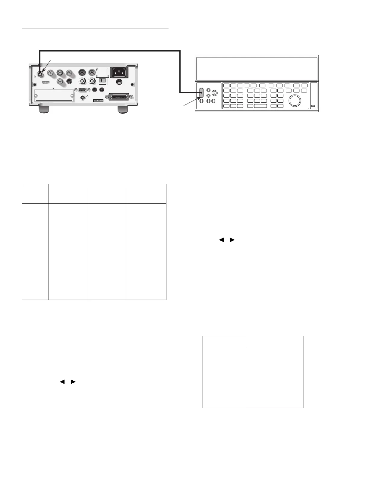
Low-noise Coax BNC Cable
Triax-to-BNC Adapter
Model 6517 Electrometer
BNC-to-dual
Banana Plug
Adapter (Connect
Cable Shield to
Output LO)
DC Current Calibrator
Figure 2-4
Connections for 20µA–20mA range calibration
16. After this step has been completed, the instrument will
prompt for the next calibration value:
CONNECT -20.00000 µA
ENTER to continue; EXIT to abort
17. Set the calibrator output to exactly -19.00000µA DC,
then press the Model 6517A ENTER key. The unit will
then display the actual calibration value:
-19.000000 µA
Use ▲, ▼, , ,ENTER,EXIT, or INFO
18. If necessary, adjust the displayed value to agree with the
calibrator current, then press the ENTER key. During
this calibration step, the unit will display the following
message:
Performing -20 µA cal
19. Repeat steps 13 through 18 for the 200µA through
20mA ranges using the calibrator current values sum-
marized in Table 2-5.
Table 2-5
Amps calibration summary (20µA-20mA ranges)
6517A range Calibration current
20µA
20µA
200µA
200µA
2mA
2mA
20mA
20mA
19.00000µA
-19.00000µA
190.0000µA
-190.0000µA
1.900000mA
-1.900000mA
19.00000mA
-19.00000mA