Calibration
2-12
Step 6: Temperature Calibration
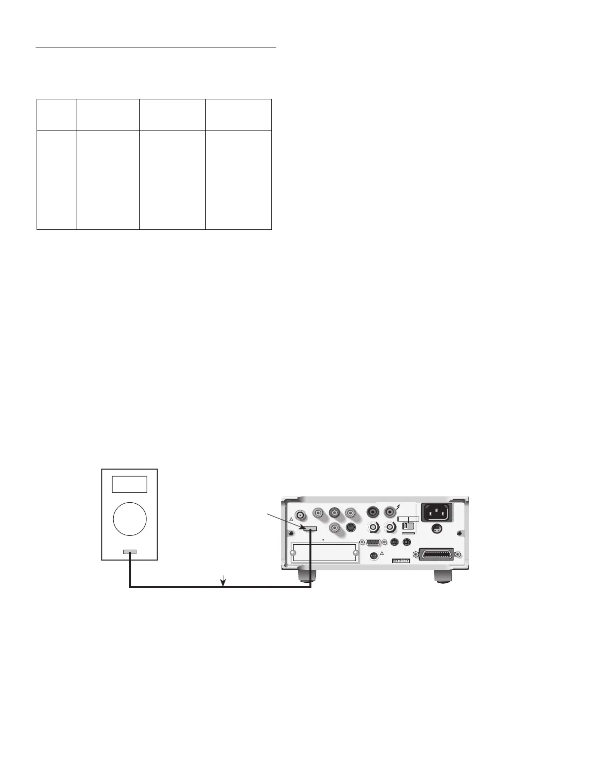
1. Connect the thermocouple calibrator to the Model
6517A EXT TEMP jack, as shown in Figure 2-6.
2. At the end of the coulombs calibration phase, the instru-
ment will prompt you for the first temperature calibra-
tion point:
CONNECT 0V/0°C
ENTER to continue; EXIT to abort
Table 2-6
Coulombs calibration summary
6517A
range
Calibration
voltage
Standard
1
capacitance
Nominal
2
charge
2nC
2nC
20nC
20nC
200nC
200nC
2µC
2µC
1.900000V
-1.900000V
19.00000V
-19.00000V
1.900000V
-1.900000V
19.00000V
-19.00000V
1nF
1nF
1nF
1nF
100nF
100nF
100nF
100nF
1.9nC
-1.9nC
19nC
-19nC
190nC
-190nC
1.9µC
-1.9µC
1
Nominal capacitance standard shown. Refer to calibration data for
actual value.
2
Charge calculated from: Q = CV, where C is capacitance standard
value, and V is the calibrator voltage. When using the Model 5156
Electrometer Calibration Standard, the Model 6517A automatically
calculates the charge from the actual capacitance value and the applied
calibrator voltage.
WARNING:
NO INTERNAL OPERATOR SERVICABLE PARTS,SERVICE BY QUALIFIED PERSONNEL ONLY.
WARNING:
NO INTERNAL OPERATOR SERVICABLE PARTS,SERVICE BY QUALIFIED PERSONNEL ONLY.
CAUTION:
FOR CONTINUED PROTECTION AGAINST FIRE HAZARD,REPLACE FUSE WITH SAME TYPE AND RATING.
CAUTION:
FOR CONTINUED PROTECTION AGAINST FIRE HAZARD,REPLACE FUSE WITH SAME TYPE AND RATING.
INPUT
250V PEAK
!
LINE RATING
50-60HZ
50VA MAX
AC ONLY
LINE FUSE
SLOWBLOW
1/2A 90-125V
1/4A 180-250V
IEEE-488
(CHANGE IEEE ADDRESS
WITH FRONT PANEL MENU)
DIGITAL
I/O
TRIG LINK
115V
LO
HI
RS232
!
MADE
IN
U.S.A.
PREAMP OUT
250 PEAK
COMMON 2V ANALOG
OUTPUT
TEMP
TYPE K
HUMIDITY
OPTION SLOT
V SOURCE
EXT TRIG
IN
MTR COMP
OUT
INTERLOCK
SELECTED
LINE VOLTAGE
90-110V
105-125V
180-220V
210-250V
1010V
PEAK
750V
PEAK
EXT Temp
Jack
Type K
Thermocouple Wire
Model 6517 Electrometer
Type K
Thermocouple Simulator/Calibrator
Figure 2-6
Connections for temperature calibration
3. Set the thermocouple calibrator output to 0°C (0mV),
then press the Model 6517A ENTER key. During this
step, the instrument will display the following:
Performing 0 V Temp Calibration
4. Next, the instrument will prompt you for the 100°C
(4.095mV) calibration point:
CONNECT 4.095mV/100°C
5. Set the thermocouple calibrator output to 100°C, then
press the Model 6517A ENTER key. During this step,
the instrument will display the following message:
Performing 4.095mV Temp Calibration
Step 7: Voltage Source Calibration
WARNING
Hazardous voltages will be present
when performing the following steps.
Avoid touching terminals while per-
forming these procedures.
1. After temperature calibration has been completed, the
instrument will prompt you to connect the voltmeter to
the voltage source output jacks:
V-SOURCE CALIBRATION
Connect Vsource to voltmeter
2. Select the DCV function and the auto-range mode on the
DMM.