SURGE OVERLOAD ALARM
The motor’s current drawdown has increased very quickly
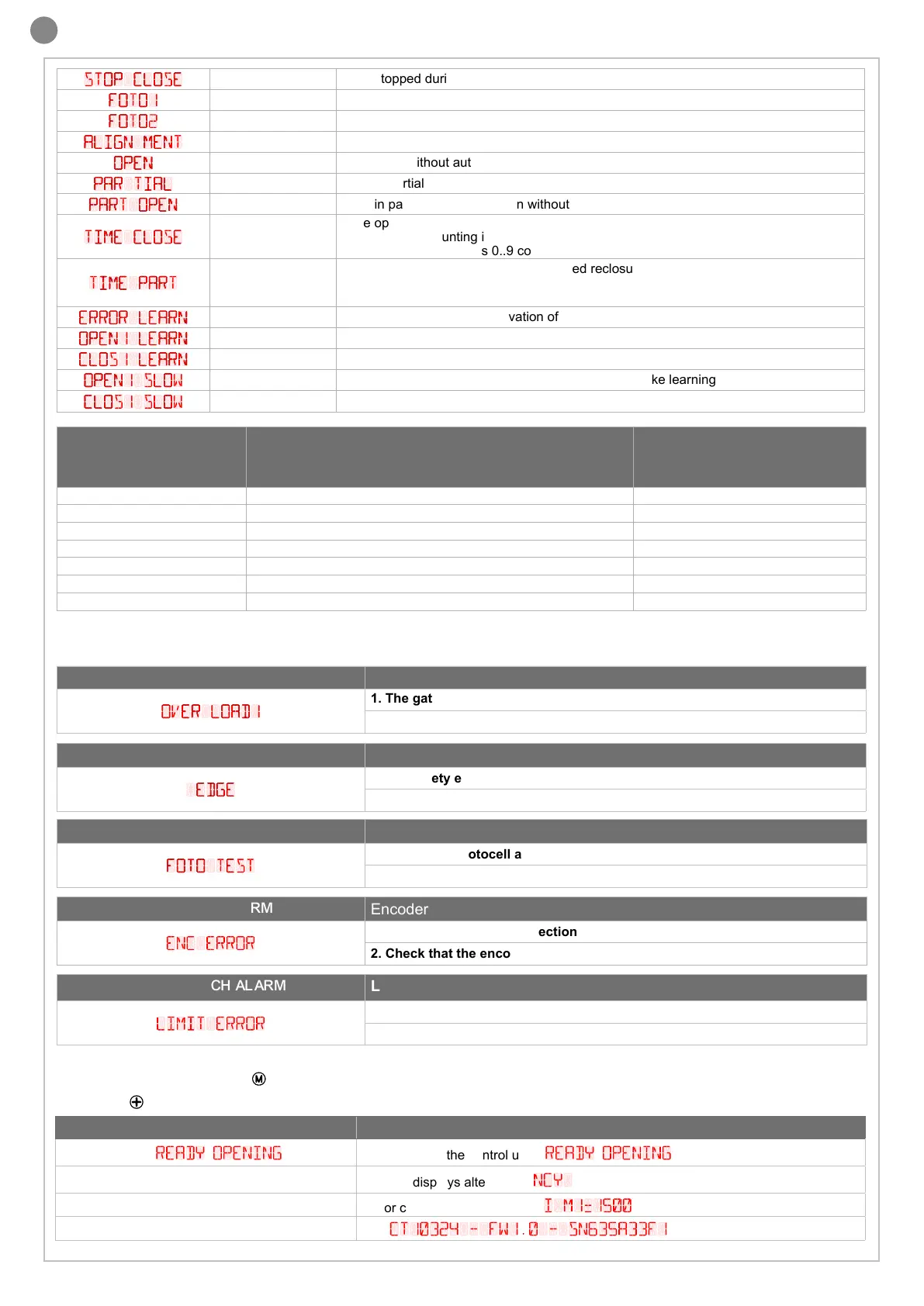
OVER LOAD1
1. The gate has hit an obstacle (M1)
2. There is friction on the leaf of M1
SAFETY EDGE ALARM
The control unit has received a signal from the safety edge
EDGE
1. The safety edge has been pressed.
2. The safety edge is not connected correctly
24
EN
Malfunctions
This section lists a number of malfunctions which may occur.
EVENT DESCRIPTION
KEY TO MAIN CONTROL
FLASHING LIGHT AND KEY
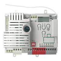
LEDS CONTROL UNIT
Autolearning During the programming phase 2 quick ashes + pause + 1 ash
Obstacle M1 Motor 1 obstacle detected 4 quick ashes + pause, 3 times
Photo 1! / Photo 2! Photocell 1 tripped / Photocell 2 tripped 2 quick ashes + pause, 3 times
Safety Edge! Safety edge tripped 5 quick ashes + pause, 3 times
Phototest Error Phototest error detected 3 quick ashes + pause, 3 times
Flash/Ind/Led Error Line overload in ash / courtesy lights / electric lock / gate light 6 quick ashes + pause, 3 times
Encoder Error Encoder error detected (only for up-and-over-door) 7 quick ashes + pause, 3 times
After eliminating the cause of the alarm, to eliminate the error message you must give an opening or closing command from the
limit switch, or press “MENU” (
) button.
Press “UP“ (
) button to read the following parameters on display.
PHOTOCELL ALARM/SAFETY EDGE
Phototest fail outcome
FOTO TEST
1. Check the photocell and the safety edge connections
2. Check that the photocells and the safety edge are operating correctly
DISPLAY MEANING
Status display (
ready
,
opening
... etc) Description of the control unit (
r
eady
,
opening
... etc)
Maneuvers performed
Counter displays alternating
ncy
and the number of cycles
Motor current 1 [mA]
Motor current absorption (e.g.
i m1=1500
)
Firmware version and serial number
E.g.
ct10324 - fw1.0 - sn635a33f1
ENCODER ALARM
Encoder do not respond
enc error
1. Check the encoder connection
2. Check that the encoder is operating correctly
LIMIT SWITCH ALARM
Limit switch fail
limit error
1. Check the limit switch connection
2. Check that the limit switch are operating correctly
STOP CLOSE
SC
Gate stopped during closure
FOTO1
F1
Photocell 1 tripped
FOTO2
F2
Photocell 2 tripped
ALIGN MENT
ALI
Re-alignment procedure
OPEN
oP
Gate open without automatic reclosure
PAR TIAL
OPD
Gate in partial opening mode
PART OPEN
Pe
Gate in partial opening position without automatic reclosure
TIME CLOSE
-tC
Gate open with timed reclosure
Flashing dash counting in progress
Dash replaced by gures 0..9 countdown (last 10s)
TIME PART
-tP
Gate in partial opening position with timed reclosure
Flashing dash counting in progress
Dash replaced by gures 0..9 countdown (last 10s)
ERROR LEARN
L--
Learning stopped due to activation of safety device or motor reverse
OPEN1 LEARN
LOP
Learning on M1 opening
CLOS1 LEARN
LCL
Learning on M1 closing
OPEN1 SLOW
SOP
Point of M1 deceleration on opening (only during stroke learning)
CLOS1 SLOW
SCL
Point of M1 deceleration on closing (only during stroke learning)
 Loading...