23
EN
PHOTO 1
The PHOTO1 contact must be connected to the COM and PH 1
terminals. To bypass the photocell, move the right-hand dip
switch upwards. After having activated the dip switch, the
PH1 LED starts to ash at a fast rate.
ATTENTION !
ACONFIRM PH1 INPUT DEACTIVATION
BY PRESSING THE AND BUTTONS SIMULTANEOUS-
LY AND HOLDING THEM DOWN UNTIL THE PH1 LED STOPS
FLASHING.
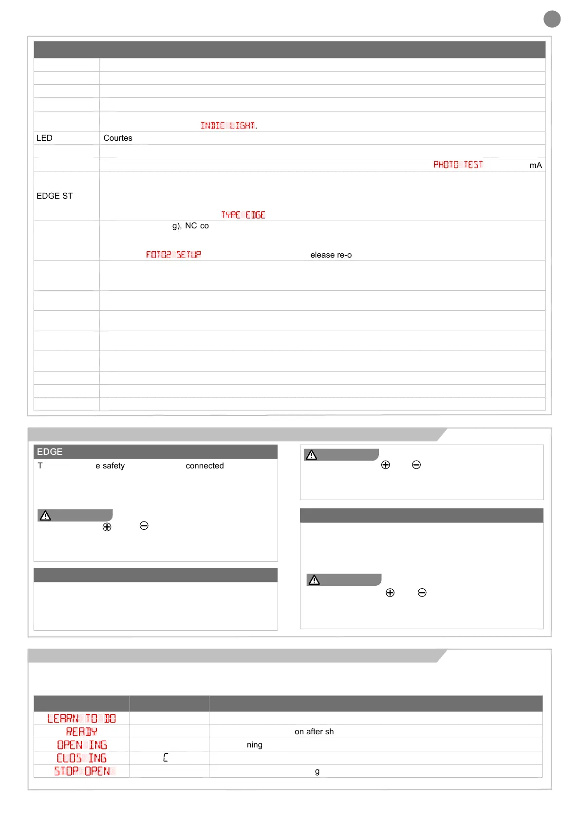
SAFETY AND CONTROL DEVICE CONNECTORS
24 VAC Accessories power supply 24 Vac without regulation. Not active if operated with batteries.
24 VAC Accessories power supply 24 Vac without regulation. Not active if operated with batteries.
COM Common for the FLASH-IND-LED outputs
FLASH Flashing light output 24Vdc (without regulation), maximum 15W
IND/ELEC
IND output for gate open indicator light 24 Vdc not regulated 5W MAX / Electric lock output 12Vac, 15VA maximum
selectable with parameter
indic light
.
LED Courtesy light output 24Vdc (without regulation), maximum 15W, controllable also via radio ON-OFF command
NEG Photocell power supply negative
PH-POW
Photocells PH1 and PH2 power supply positive; phototest can be selected with parameter
PHOTO TEST
24 Vdc, 200 mA
EDGE STOP
EDGE safety device, NC contact between EDGE and EDGE (warning, with dip switch 1 ON the safety device input is o).
This input is classied as a safety device; the contact can be deactivated at any time, cutting out the automation system
and disabling all functions, including Automatic Closure.
Safety sensor edge, ON/OFF, NC contact or resistive 8K2 between EDGE and EDGE.
Input selectable with parameter
TYPE EDGE
PH2
Photocells (opening), NC contact between PH2 and COM (warning, with dip switch 2 ON the PHOTOCELL 2 safety
device input is o). The photocell is tripped at any time during opening of the automation system, halting operation imme-
diately; the automation system will continue opening when the contact is restored. In the event of intervention on closure
(parameter
FOTO2 SETUP
= 0) the device stops and on release re-opens
PH1
Photocells (closing), NC contact between PH1 and COM (warning, with dip switch 3 ON the PHOTOCELL 1 safety devi-
ce input is o) The photocell is tripped at any time during closing of the automation system, halting operation immediately
and reversing the travel direction
OPEN
OPEN command NO contact between OPEN and COM
Contact for the HOLD-TO-RUN function. The gate OPENS as long as the contact is held down
CLOSE
CLOSE command NO contact between CLOSE and COM
Contact for the HOLD-TO-RUN function. The gate CLOSES as long as the contact is held down
PAR
PARTIAL command NO contact between PAR and COM
Used to open the gate partially, depending on the software setting (not active up-and-over door)
SBS
STEPPING command NO contact between SBS and COM
Open/Stop/Close/Stop command, or as set in the software
COM Common for the PH2-PH1-OPEN-CLOSE-PAR-SBS inputs
SHIELD Antenna - shield
ANT Antenna - signal
In “NORMAL OPERATING MODE”, i.e. when the system is powered up normally, the 5-gure LCD display shows the following status messages
(to compare with the previous electronic board CT10224 check the second column):
CT10324 OLD CT10224 MEANING
LEARN TO DO
Learning not done
READY
--
Gate closed or switch-on after shutdown
OPEN ING
’
OP
Gate opening
CLOs ING
CL
Gate closing
STOP OPEN
SO
Gate stopped during opening
EDGE
The inputs of the safety EDGE must be connected to the EDGE
and EDGE terminals. To bypass the safety edge, move the
left-hand dip switch upwards. After having activated the dip
switch, the EDGE LED starts to ash at a fast rate.
ATTENTION !
CONFIRM EDGE INPUT DEACTIVATION
BY PRESSING
AND BUTTONS SIMULTANEOUSLY
AND HOLDING THEM DOWN UNTIL THE EDGE LED STOPS
FLASHING.
PHOTO 2
The PHOTO2 contact must be connected to the COM and PH
2 terminals. To bypass the photocell, move the middle dip
switch upwards. After having activated the dip switch, the
PH2 LED starts to ash at a fast rate.
ATTENTION !
CONFIRM PH2 INPUT DEACTIVATION
BY PRESSING THE
AND BUTTONS SIMULTANEOUSLY
AND HOLDING THEM DOWN UNTIL THE PH2 LED STOPS
FLASHING.
4.3 - Display during normal operation
4.2 - Disabling the safety devices
 Loading...


