Installation 2
Keysight 11713D/E Operating and Service Manual 31
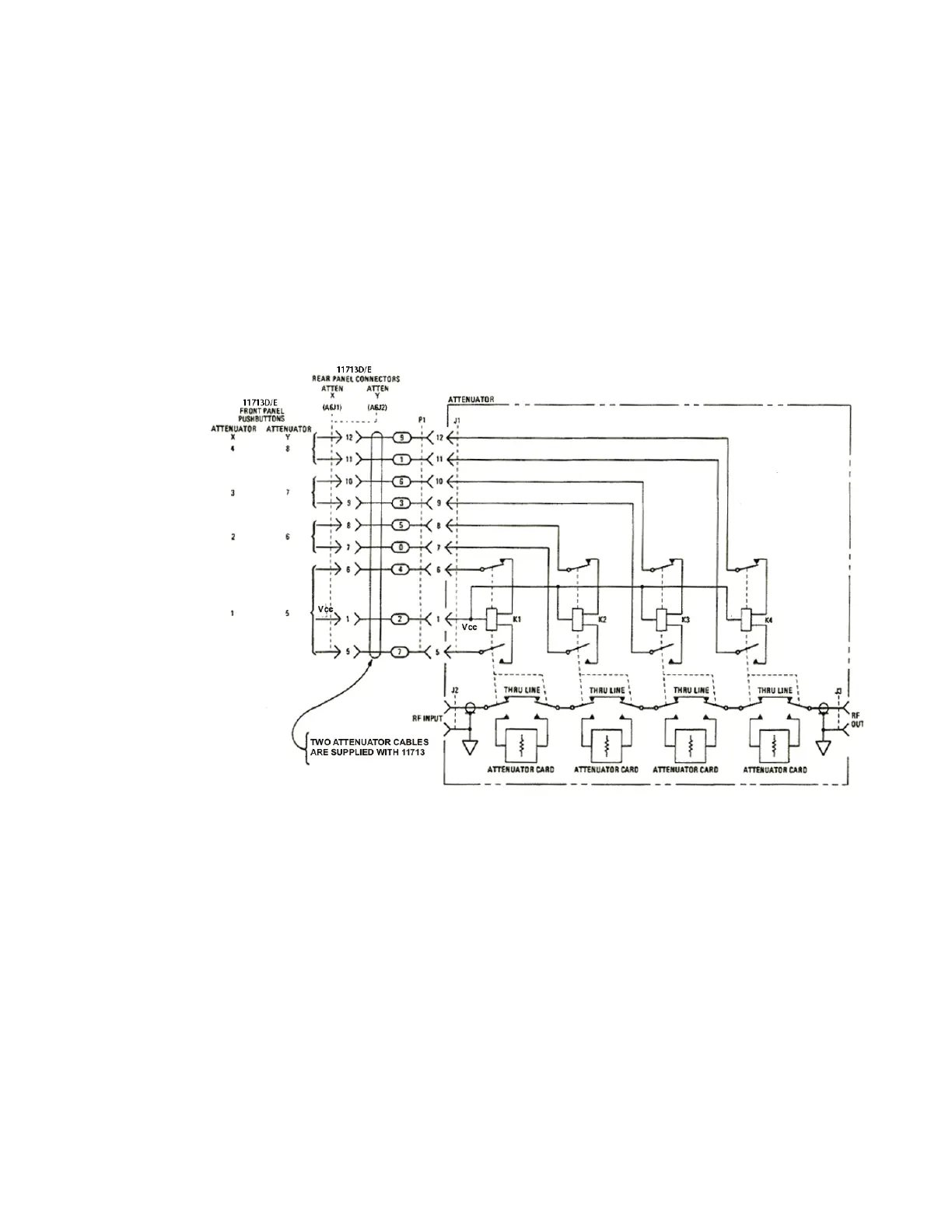
Driving four-section attenuators and switches
– To use one four-section attenuator assembly, connect an attenuator interface cable either to
the ATTEN X output (A6J1) or ATTEN Y output (A6J2). Connect all outputs (two for 11713D and
four for 11713E) to have more than four attenuator segments.
– A typical connection for a programmable four-section attenuator to 11713D is illustrated in
Figure 2-2, together with pin number for each connector.
– Using these same connections to Keysight 8762 or 8765 series coaxial switches, control can be
extended to number of switches in multiple of four. If S9 and S0 outputs are utilized, 11713D
and 11713E can drive up to 10 switches and 20 switches respectively.
Figure 2-2 Typical connection for a programmable four-section attenuator
Driving additional coaxial switches
– Make switch connections to S0 outputs, S9 outputs, or to rear panel ATTEN X output or ATTEN
Y output.
– Figure 2-3 below shows the rear panel connections to S0 outputs and the corresponding switch
positions reflected by pushbutton indicators.
– Connections to Keysight 8762 or 8765 series coaxial switches can also be made to the ATTEN X
output or ATTEN Y output as illustrated in Figure 2-2.