Introduction 1
Keysight 11713D/E Operating and Service Manual 23
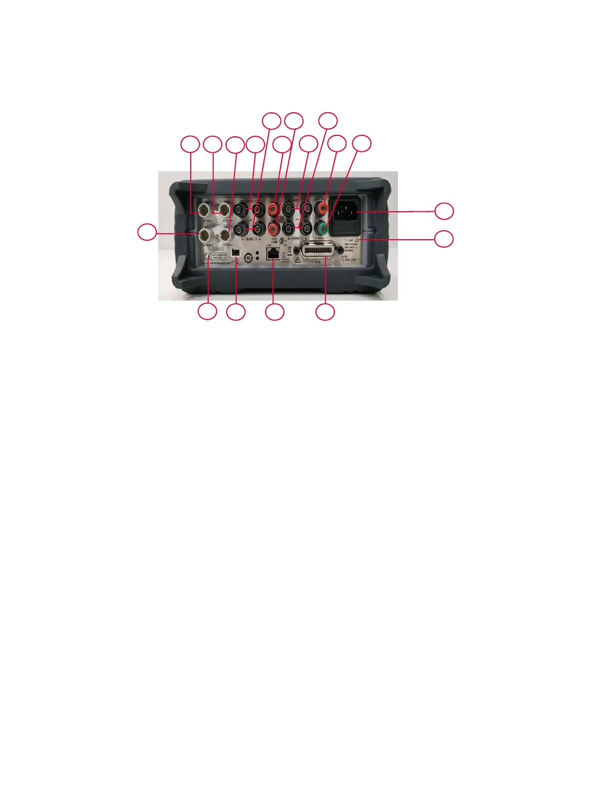
This section briefly describes the function of the rear panel connectors of 11713E.
Figure 1-4 11713E rear panel features
1 ATTEN X Bank 1: Viking connector for connection to attenuator or switch(es), for bank 1.
2 ATTEN X Bank 2: Viking connector for connection to attenuator or switch(es), for bank 2.
3 ATTEN Y Bank 1: Viking connector for connection to attenuator or switch(es), for bank 1.
4 ATTEN Y Bank 2: Viking connector for connection to attenuator or switch(es), for bank 2.
5 S9 A/B Bank 1: Banana jack connectors for connection to coaxial switch, for bank 1.
6 S9 A/B Bank 2: Banana jack connectors for connection to coaxial switch, for bank 2.
7VDC COM Bank 1: Banana jack connector to provide common Vdc in driving the coaxial
switches connected to S9 and/or S0, for bank 1.
8VDC COM Bank 2: Banana jack connector to provide common Vdc in driving the coaxial
switches connected to S9 and/or S0, for bank 2.
9 S0 A/B Bank 1: Banana jack connectors for connection to coaxial switch, for bank 1.
10 S0 A/B Bank 2: Banana jack connectors for connection to coaxial switch, for bank 2.
11 EXT (External) VDC: Banana jack connector to provide user-defined Vdc, for both banks.
12 GND (Ground): Banana jack connector to provide grounding, for both banks.
13 Receptacle: Matches transformer primary to line voltage via power cable.
14 Alert symbol: This symbol is used to point out a necessary reference for the user.
15 GPIB connector: The interface connector from a source device to a listening device for the
remote mode of operation.
16 LAN connector: The interface connector for LAN cable.
17 USB connector: The interface connector for Type mini B 5-pin USB cable.
18 Instrument markings
1
2
3
4
7
8
9
10
11
5
6
12
13
151617
14
18