Installation 2
Keysight 11713D/E Operating and Service Manual 33
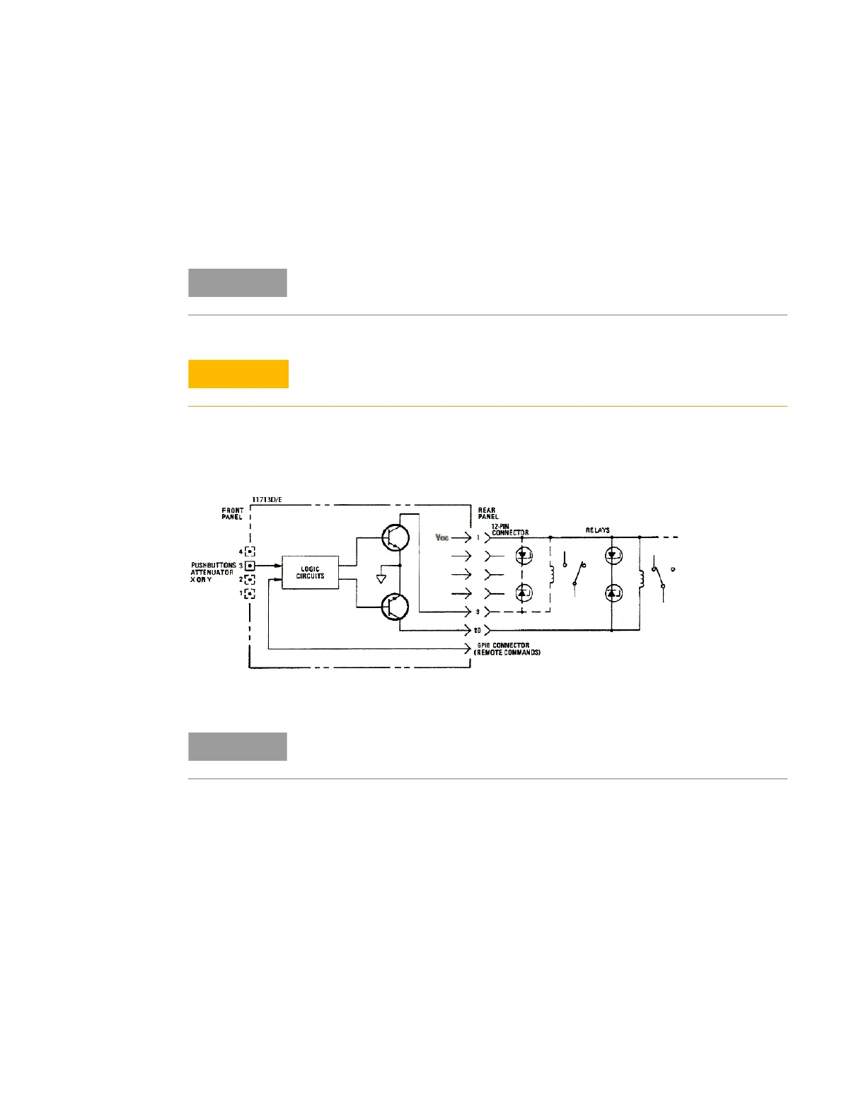
Driving relays
– To drive ten devices for 11713D, connect attenuator cables at ATTEN X and Y and switch cables
to S9 and S0.
– A total of 10 relays may be on at one time if the total current is less than 3.4 A. However, since
there are dual transistor and relay drivers, where one driver is on while the other is off, a total of
20 relays may be controlled.
– Figure 2-4 below shows the connections for a simplified relay driving circuit. The circuit is
adaptable for simple non-latching relays.
Figure 2-4 Typical connection for relay driving circuit
11713E is capable of driving double the amount of devices that 11713D can.
However, the total load current that can be consumed is still 3.4 A.
If the total load current of 3.4 A is exceeded, damage may result.
It is also recommended that two 28.7 V zener diodes be connected
back-to-back across the relay coils to reduce voltage transients.