Getting Started 1
Keysight 53150A/151A/152A Operating Guide 29
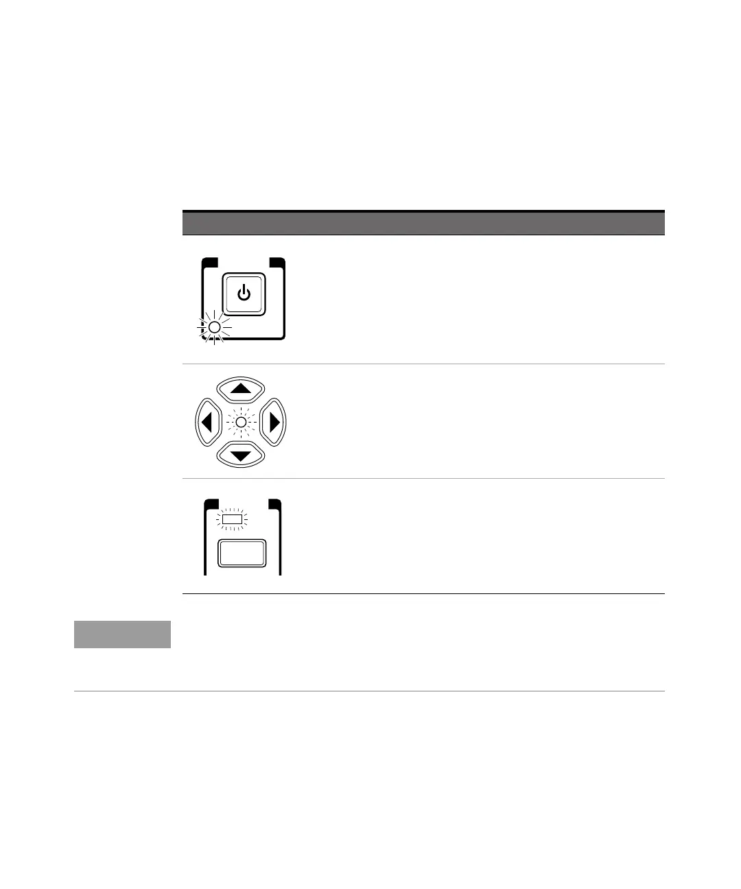
The Front Panel Indicators at a Glance
The front panel includes three LED indicators. These are listed and described in
the following table.
Indicator Description
The Standby indicator is lit whenever the Main ~ Power switch on the rear
panel is turned ON, and the POWER switch on the front panel is OFF (out).
During Standby, most of the instrument’s circuits do not receive power.
However, the timebase and the cooling fan are powered so that the
temperature in the timebase components remains stable, and if the Battery
option is installed, the battery-charging circuits are powered. When you press
the POWER switch on the front panel, the Standby indicator goes off, and all
of the Counter’s circuits receive power.
When the LED indicator between the arrow keys flashes, the arrow keys can be
used to navigate and change values in menus.
When you make a change in a menu, always press the Enter key to save the
setting and exit the menu.
The Gate LED indicator flashes to indicate the rate at which measurements are
triggered. The flash rate of the LED varies with the settings of the
measurement rate (Rate key) and the measurement resolution (Resol key).
The flash rate of the LED provides a rough indication of the number of
measurements that are being taken in a given period of time.
POWER
Standby
FREQ
Gate
Chan
Select
NOTE
It is normal for the fan in the Counter to run when the Counter is in Standby
mode. Power is supplied to the timebase whenever the Main ~ Power switch is
on to maintain long term measurement reliability, and the fan helps maintain
timebase temperature stability.