Getting Started 1
Keysight 53150A/151A/152A Operating Guide 53
Using Power Correction
The Power Correction function in the main Menu allows you to set the Counter to
automatically compensate for power loss (or gain) that occurs in the test
configuration, such as attenuation resulting from cable impedance. You can
choose from nine power-correction profiles that are stored in nonvolatile memory,
and you can modify the contents of these profiles.
Each profile is defined by two to ten data points (a data point consists of
a loss value and a frequency value). When Power Correction is enabled, the
Counter automatically adds a correction to the power reading (determined from
the data points in the profile) that compensates for the loss (or gain) at the
frequency being measured. When a measured frequency does not match any of
the frequency values defined in the currently selected profile, the Counter
interpolates for the measured frequency to determine the appropriate value to
add to the power measurement. The correction profiles require a minimum of two
data points per profile.
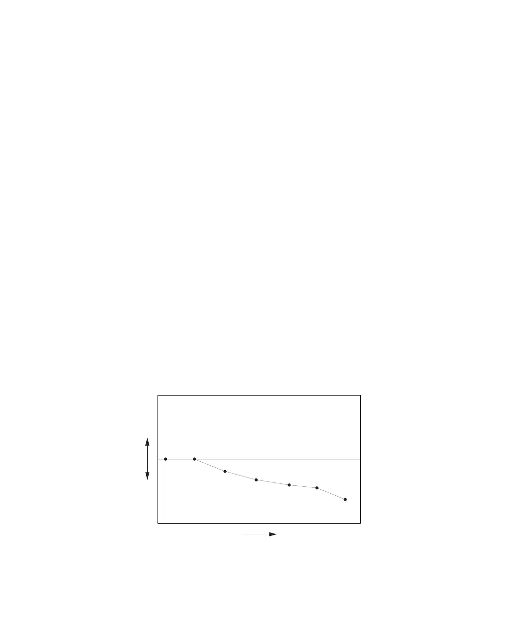
Power Correction Theory of Operation
When the Counter interpolates between data points to determine the amount of
correction to apply to the current measurement, it computes
the correction based on a straight line plotted between the frequency values in
the two closest data points. Therefore, a graph of a power-correction profile would
show a “curve” that consists of two to nine straight-line segments, rather than a
true curve, as shown below.
P
o
w
e
r
F r e q u e n c y