1 Getting Started
44 Keysight 53150A/151A/152A Operating Guide
Measuring Frequency
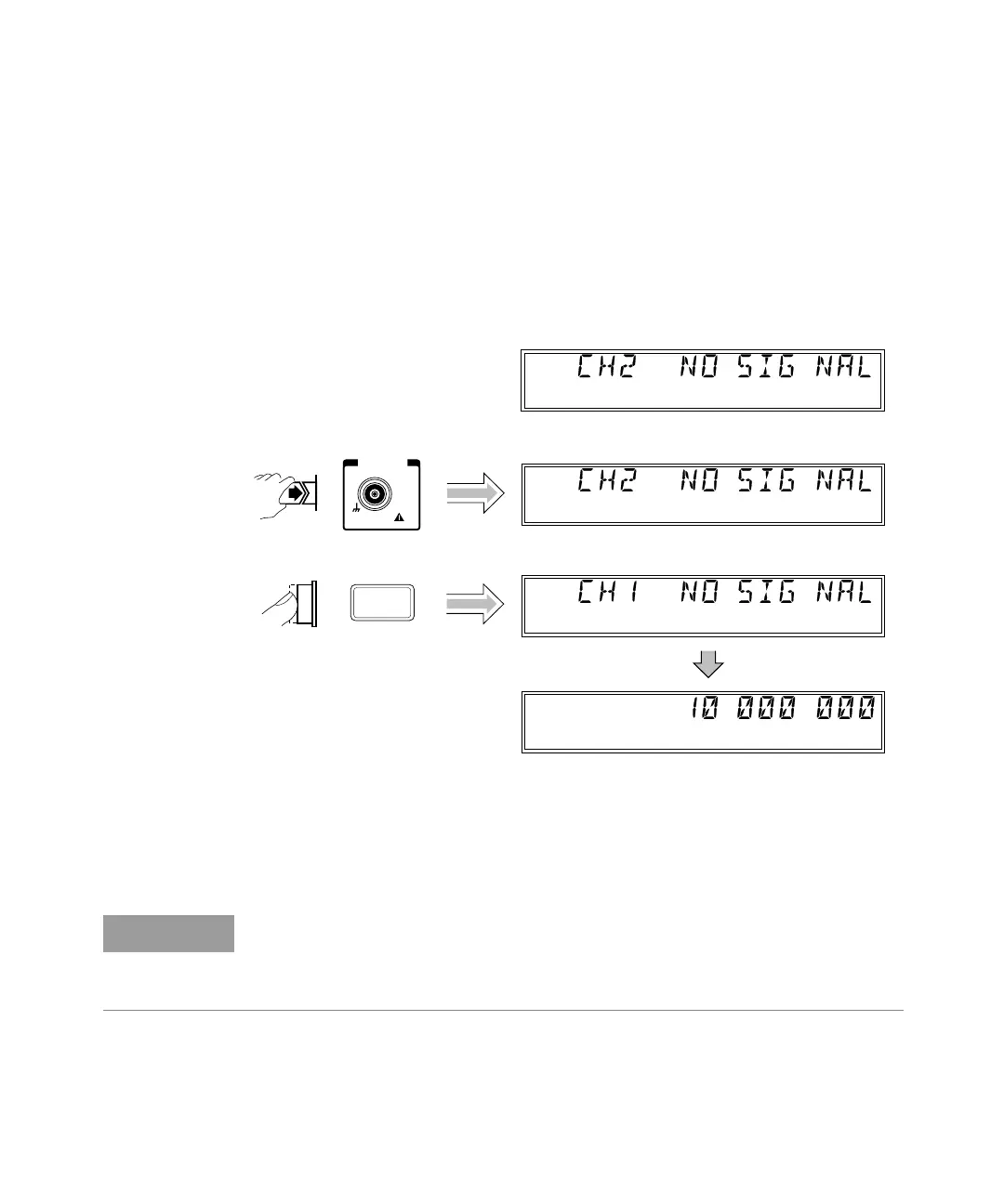
The following diagram shows the basic sequence to use to make a frequency
measurement using Channel 1. This example assumes that the Counter is on and
has completed the Self Test. For the purposes of this example, use the 10 MHz
reference output on the Counter’s rear panel as a signal source for input to
Channel 1.
The same procedure applies to making a basic frequency measurement on
Channel 2. However, since Channel 2 is automatically selected when you turn on
the Counter, the channel-selection step is unnecessary (unless you previously
selected Channel 1).
Ch 2
Freq
Ch 1
Freq
Chan
Select
Ch 1
Freq
CHANNEL 1
1M
DAMAGE
+30 dBm
10 Hz to 125 MHz
Ch 2
Freq
NOTE
The Channel 2 input path circuits contain sensitive GaAs semiconductors. To
prevent damage to these components, always adhere to standard ESD
(Electro-Static Discharge) prevention procedures, and ensure that the maximum
power specification for this channel (+27 dBm) is not exceeded.