114
For other connections by using the module selector, use the following connections
depending on the measurement parameters.
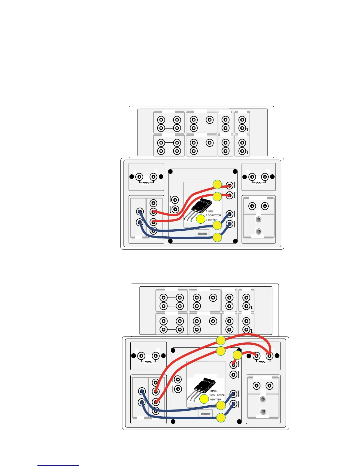
For each connection, open the N1259A test fixture cover, and connect the test leads
by following the numbers on the drawing.
Note: There is no step by step connection instruction in this section.
●
Ic – Vceo connection
A2-3-2. Other connections
1
2
1
2
3
1
2
Force
Force
Force
Force
Force
Sense
Sense
Sense
Sense
Guard
Guard
Guard
High
Sense
Force
Low
High
Low
1 2 3
1 kΩ
100 kΩ
MF CMU
DC Bias Input
High Voltage Bias-Tee
Module Selector Output
Agilent N1259A opt 022Agilent N1259A opt 033
Agilent N1259A opt 010
HCSMU1
HCSMU2 HPSMU2
HPSMU1
GNDU1
11
1
AUX2
AUX1
HVSMU1
High
Low
Signal
Signal
Force
Force
Force
Force
Force
Force
Sense
Sense
Sense
Sense
Guard
Guard
Guard
Low
High
Sense
1
2
3
4
5
1
2
1
2
3
1
2
Force
Force
Force
Force
Force
Sense
Sense
Sense
Sense
Guard
Guard
Guard
High
Sense
Force
Low
High
Low
1 2 3
1 kΩ
100 kΩ
MF CMU
DC Bias Input
High Voltage Bias-Tee
Module Selector Output
Agilent N1259A opt 022Agilent N1259A opt 033
Agilent N1259A opt 010
HCSMU1
HCSMU2 HPSMU2
HPSMU1
GNDU1
11
1
AUX2
AUX1
HVSMU1
High
Low
Signal
Signal
Force
Force
Force
Force
Force
Force
Sense
Sense
Sense
Sense
Guard
Guard
Guard
Low
High
Sense
1
2
4
5
3
6
Figure A2-7. Ic–Vceo connection with no resistor.
Figure A2-8. Ic–Vceo connection with 100 kΩ
ΩΩ
Ω resistor.
●
Ic – Vceo connection with 100 kΩ
ΩΩ
Ω resistor.

 Loading...


