116
●
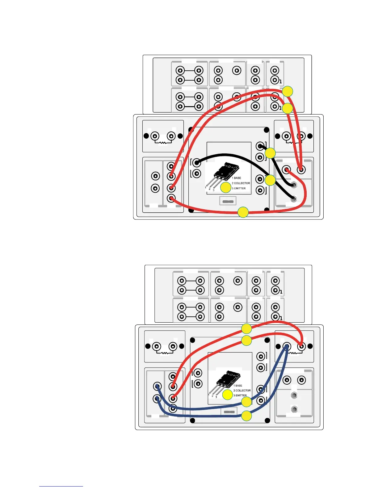
Cob application test connection.
Use SHV cable and an adaptor for connections in step 5 and step 6.
●
Connection for 100 kΩ
ΩΩ
Ω resistor measurement
Figure A2-11. Cob application test connection.
Figure A2-12. Connection for 100 kΩ
ΩΩ
Ω resistor measurement.
1
2
1
2
3
1
2
Force
Force
Force
Force
Force
Sense
Sense
Sense
Sense
Guard
Guard
Guard
High
Sense
Force
Low
High
Low
1 2 3
1 kΩ
100 kΩ
MF CMU
DC Bias Input
High Voltage Bias-Tee
Module Selector Output
Agilent N1259A opt 022Agilent N1259A opt 033
Agilent N1259A opt 010
HCSMU1
HCSMU2 HPSMU2
HPSMU1
GNDU1
11
1
AUX2
AUX1
HVSMU1
High
Low
Signal
Signal
Force
Force
Force
Force
Force
Force
Sense
Sense
Sense
Sense
Guard
Guard
Guard
Low
High
Sense
1
3
2
5
6
4
1
2
1
2
3
1
2
Force
Force
Force
Force
Force
Sense
Sense
Sense
Sense
Guard
Guard
Guard
High
Sense
Force
Low
High
Low
1 2 3
1 kΩ
100 kΩ
MF CMU
DC Bias Input
High Voltage Bias-Tee
Module Selecto r Output
Agilent N1259A opt 022Agilent N1259A opt 033
Agilent N1259A opt 010
HCSMU1
HCSMU2 HPSMU2
HPSMU1
GNDU1
11
1
AUX2
AUX1
HVSMU1
High
Low
Signal
Signal
Force
Force
Force
Force
Force
Force
Sense
Sense
Sense
Sense
Guard
Guard
Guard
Low
High
Sense
1
2
4
5
3

 Loading...