117
The 40 A output is realized by connecting two HCSMUs in parallel using 16493S Opt
021 Dual HCSMU Combination Adapter.
Therefore, 40 A configuration is possible only when two HCSMUs are installed in
the B1505A as shown in figure A3-1. Use this configuration if your device requires
more than 20 A current.
Note: Limitation
In this configuration, 2 x HCSMU is used for Collector supply.
Therefore, HPSMU is used for the Base supply, but the maximum
current from HPSMU is limited to maximum 1 A. Therefore, the
hFE of your device needs to be at least 20 (desirable around 40)
at the measurement condition to drive the collector to output
more than 20 A and to receive the benefit of this configuration.
Tips:
If the hFE of your device is very small (say, 10 as an example) in
your measurement condition, then using the 20 A configuration
(one HCSMU is used for collector supply and the other HCSMU
for the base supply) can drive the collector to a full 20 A rather
than 10 A (limited by base SMU) in the 40 A configuration.
The following B1505A configuration is used for the 40 A solution.
You can use the same sample example files by just replacing the corresponding
SMU names.
Agilent B1505A Power Device Analyzer/Curve Tracer:
●
1 X HVSMU (B1513A) High Voltage SMU
●
2 X HCSMU (B1512A) High Current SMU
●
1 X HPSMU (B1510A) High Power SMU
●
1 X MFCMU (B1520A) Multi-Frequency CMU
Cables:
●
2 X 16493S HCSMU Cable
●
1 X 16493T HV Triax Cable
●
2 X 16494A Triax Cable
●
1 X 16493L GNDU Cable
●
1 X N1300A CMU Cable
●
1 X 16493J Interlock Cable
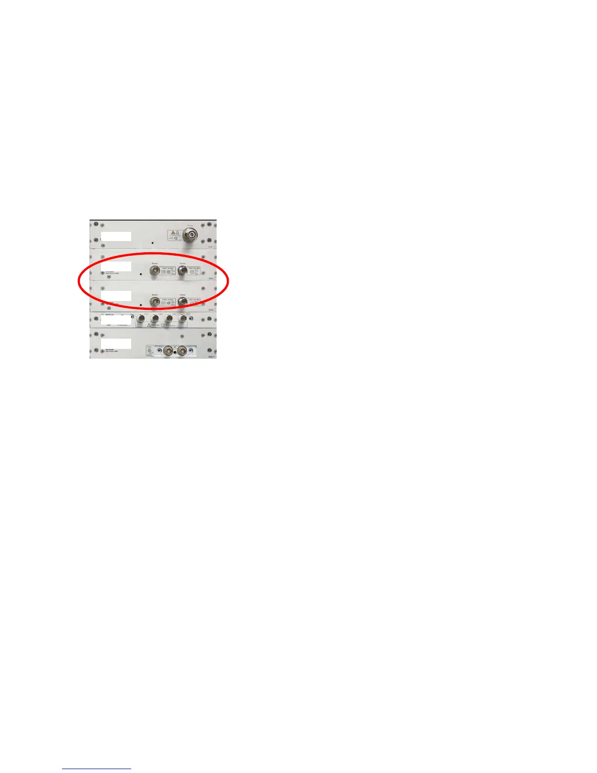
Appendix 3. Configuration for 40 A output
A3-1. Instruments and Accessories used for 40 A configuration
HCSMU
MFCMU
HVSMU
HPSMU
HCSMU
Two HCSMU configuration.
Figure A3-1. B1505A configuration
for 40 A output.

 Loading...