119
Step number 1:
Using a 16493J Interlock Cable, connect the Interlock on the B1505A and the
Interlock on the N1259A
Tips:
For connecting the interlock cable, hold the black plastic part and then turn the
connector by pressing toward the interlock connector in the instrument side as
shown in figure 2-8 in the main section.
For disconnecting the interlock cable, hold the metal part and then pull the con-
nector by turning it.
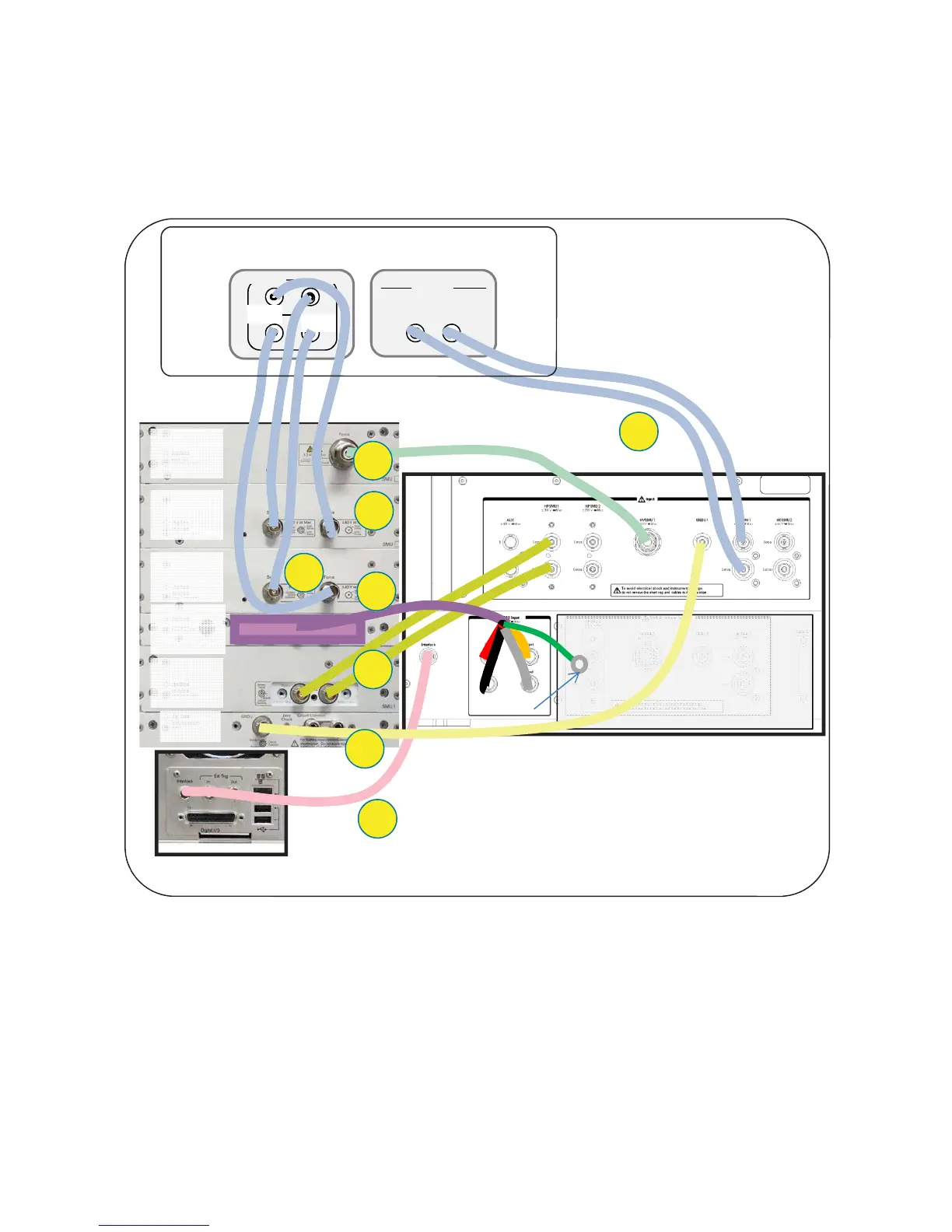
A3-2. Cable Connection between the B1505A and the N1259A Test Fixture
Back side of the B1505A
Back side of the N1259A
1
3
7
8
16493S Opt 021 Dual HCSMU Combination Adapter
Back side
Front side
Master
Slave
Force Sense
Sense Force
Output
5
6
4
B1513A
HVSMU
B1512A
HCSMU
B1510A
HPSMU
B1520A
MFCMU
GNDU
B1512A
HCSMU
2
Leave it open
Coax
Triax
Coax
Triax
Coax
Triax
Figure A3-3. Connections for 1x HPSMU and 2x HCSMU 40 A Configuration.
Connect the cables between the B1505A and the N1259A as shown in figure A3-3
by following the step number 1 to 8.
The breakdown of each steps with cable figures and the connector locations are
shown in figure A3-4.

 Loading...