39
A. Common cable configuration for Ic-Vce, hFE_Vbe-Ic and Vce(sat)-Ic 2 with
HPSMU (base) and HCSMU (collector) connection:
Open the N1259A test fixture cover, and connect the test leads shown in figure 3-2
by following the step numbers as shown in figure 3-3 and the following procedure
steps.
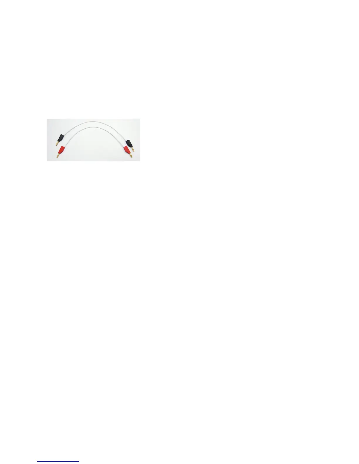
Note: The available colors of the leads are black and red only. The lead color
used in figure 3-3 is for reference only.
The numbers of the procedure steps correspond to the numbers on
the drawing for connecting the test leads.
Figure 3-2. Test Lead for the N1259A Test Fixture
[PROCEDURE]
Step 1. Insert the power BJT (example: MJL4281AG) into the socket on the N1259A.
Make sure the device pin name matches to the socket numbers shown in
figure 3-3.
Step 2. Connect the High-Force of the HCSMU1 to the terminal 2 Force (Collector)
on the Inline Package Socket.
Step 3. Connect the High-Sense of the HCSMU1 to the terminal 2 Sense (Collector)
on the Inline Package Socket.
Step 4. Connect the Low-Force of the HCSMU1 to the terminal 3 Force (Emitter) on
the Inline Package Socket.
Step 5. Connect the Low-Sense of the HCSMU1 to the terminal 3 Sense (
Emitter
)
on the Inline Package Socket.
Step 6. Connect the HPSMU1 Force to the terminal 1 Force (Base) on the Inline
Package Socket.
Step 7. Connect the HPSMU1 Sense to the terminal 1Sense (Base) on the Inline
Package Socket.
Step 8. Connect the GNDU1 Force to the terminal 3 Force (Emitter) on the Inline
Package Socket.
Step 9. Connect the GNDU1 Sense to the terminal 3 Sense (Emitter) on the Inline
Package Socket.
Close the N1259A fixture cover.

 Loading...


