45
Review:
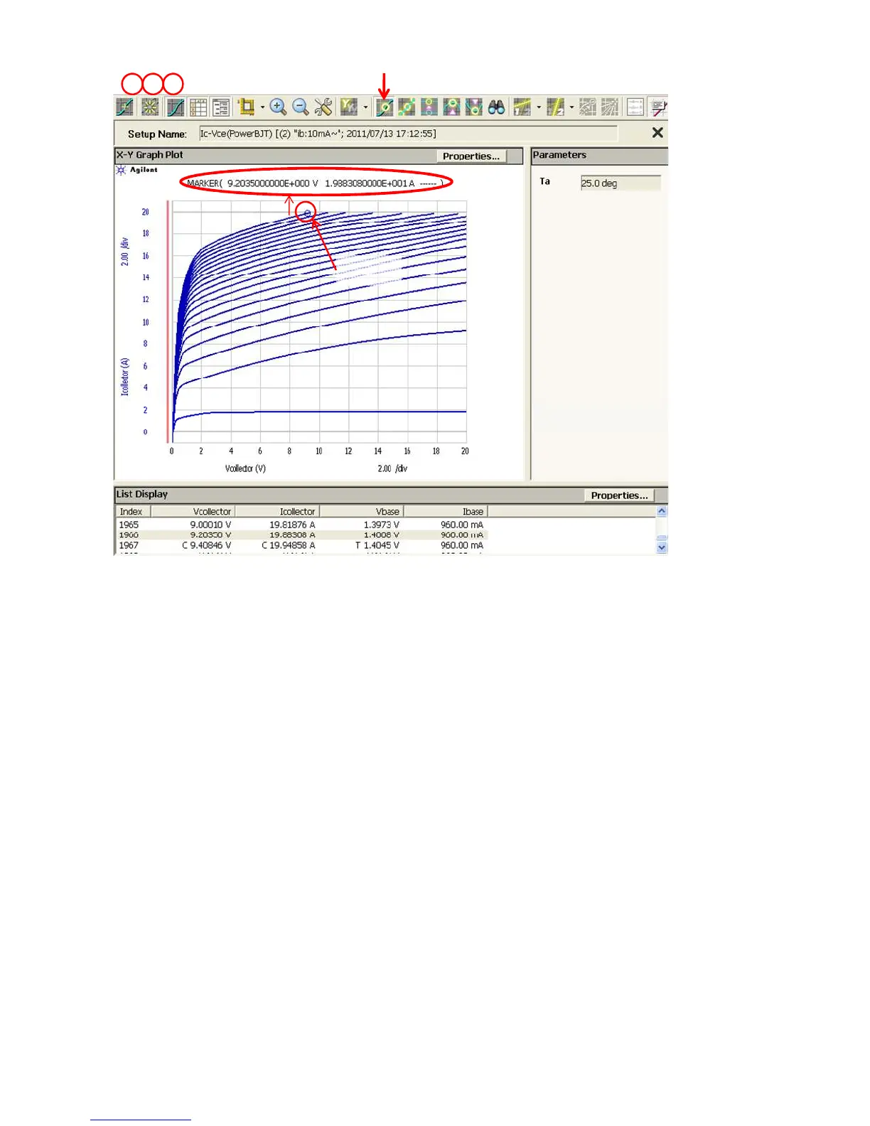
After the measurement, the marker is manually lmoved to the maximum collector
current position.
The marker function can be activated by pressing the marker on/off icon shown in
the graph. The marker appears on the first measurement point, and you can move
the measurement point by rotating the rotary knob in the primary sweep direction.
Pressing the rotary knob steps to the secondary sweep direction.
The measurement is limited at 20 A in the example which is the maximum current of
HCSMU connected to the collector, but it is also very close to the limit of HPSMU
connected to the base terminal.
The maximum collector current of the B1505A can be expanded to 40 A by connect-
ing two HCSMUs in parallel, but the maximum 1 A base current of HPSMU limits the
maximum collector current around 20 A even if you use 40A configuration that is
shown in appendix section if you use this example powerBJT.
Marker readings
76 8
Marker On/Off
Marker
Figure 3-6. Ic-Vce application test display.
 Loading...


