55
[PROCEDURE]
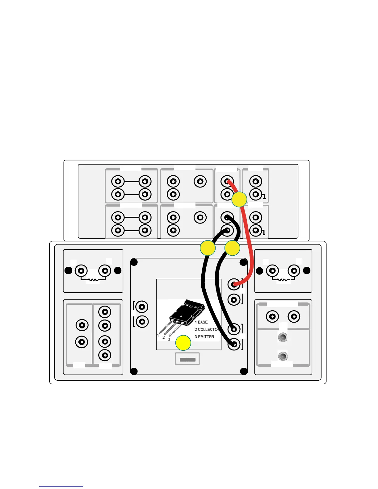
Step 1. Insert the power BJT (example: MJL4281AG) into the socket on the N1259A.
Make sure the device pin name matches to the socket numbers shown in
figure 3-11.
Step 2. Connect the Force of the HVSMU1 to the terminal 2 Force (Collector) on the
Inline Package Socket.
Step 3. Connect the GNDU1 Force to the terminal 3 Force (Emitter) on the Inline
Package Socket.
Step 4. Connect the GNDU1 Sense to the terminal 3 Sense (Emitter) on the Inline
Package Socket.
Close the N1259A fixture cover.
1
2
1
2
3
1
2
Force
Force
Force
Force
Force
Sense
Sense
Sense
Sense
Guard
Guard
Guard
High
Sense
Force
Low
High
Low
1 2 3
1 kΩ
100 kΩ
MF CMU
DC Bias Input
High Voltage Bias-Tee
Module Selector Output
Agilent N1259A opt 022Agilent N1259A opt 033
Agilent N1259A opt 010
HCSMU1
HCSMU2 HPSMU2
HPSMU1
GNDU1
11
1
AUX2
AUX1
HVSMU1
High
Low
Signal
Signal
Force
Force
Force
Force
Force
Force
Sense
Sense
Sense
Sense
Guard
Guard
Guard
Low
High
Sense
1
34
2
Figure 3-11. Ic–Vceo connection with no resistor between SMU and the collector terminal.

 Loading...


