91
Interactive sweep control:
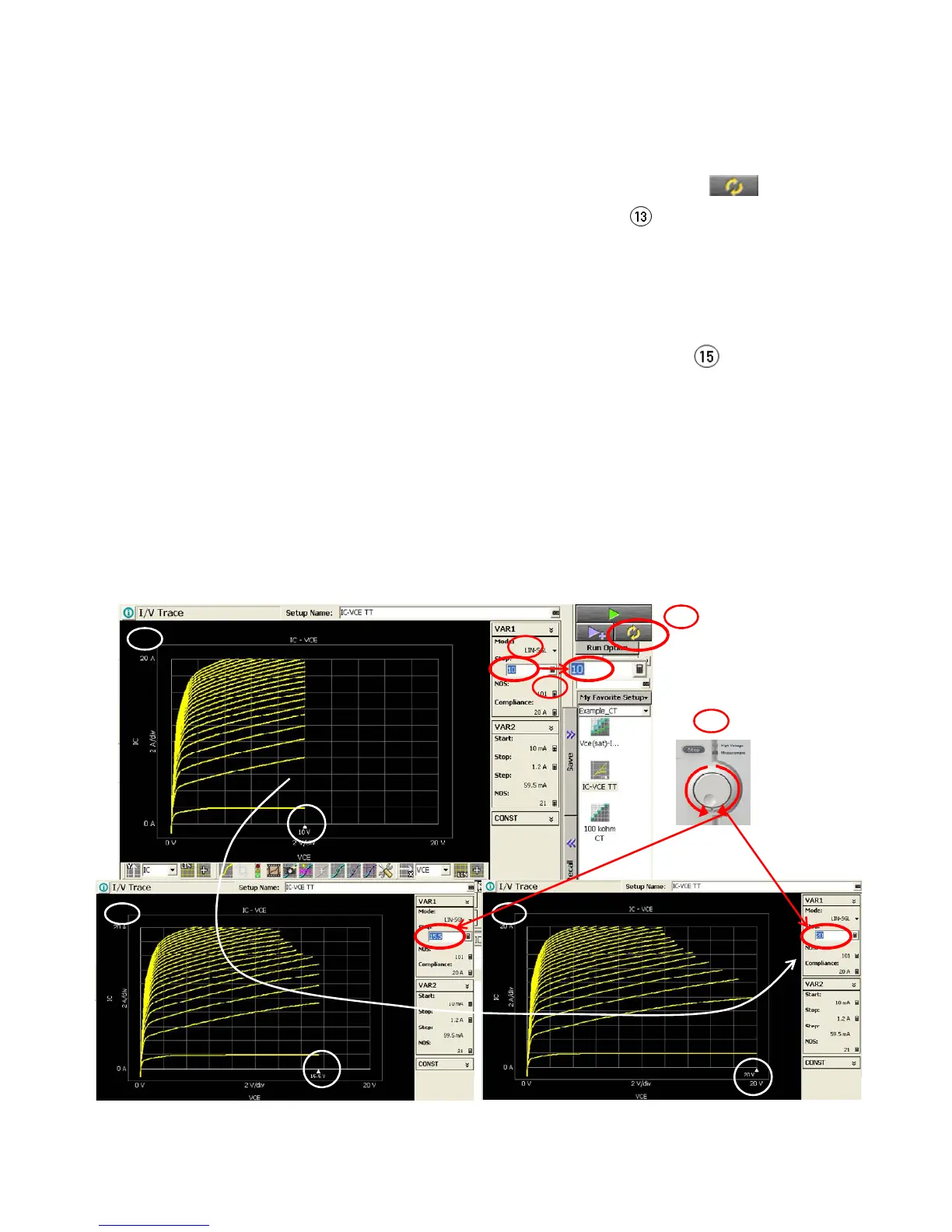
You can control the sweep by manually by following the next steps; (See figure 3-34)
Step 11. Activate Stop voltage of VAR1, and set the voltage to a lower safe voltage,
say 10 V.
Step 12. Start repeat measurement by pressing Repeat Measure button.
Step 13. The graph sweeps 0 V to +10 V marked by "step 13" in figure 3-34
(top left) is shown.
Step 14. Activate Stop voltage of VAR1 again.
Now, you can control the maximum sweep voltage by rotating a rotary
knob in real time manner.
Step 15. Rotate the knob clock wise.
The sweep end point increases as shown marked by "step
15" (bottom left) in the figure.
Step 16. Then the sweep finished at Vce=20 V in the example.
Tips:
It takes a while until all the traces are refreshed to the new sweep stop voltage in
the example setup, because there are 21 VAR2 Ib steps for each VAR1 Vce sweep.
You can reduce the VAR2 step number in the case where a faster response is re-
quired.
12
11
15
13 10 V sweep
15 @15.5 V sweep 16 @20 V sweep
14
Figure 3-34. IC-VCE TT Tracer Test: Interactive sweep control.

 Loading...


