Appendix B Digital Port Functions
100 Series E4360 User’s Guide
Front Panel:
SCPI Command:
Select
System\IO\DigPort\Pin1.
Select Function, then Fault Out.
Go back one level, select
Polarity, then either Positive or
Negative.
To configure the Fault function:
DIG:PIN1:FUNC FAUL
To select the fault output polarity:
DIG:PIN1:POL <pol>
Inhibit Input
Pin 3 can be configured as a remote inhibit input. The polarity of pin 3
can also be configured. Pin 8 is the common for pin 3.
The Inhibit Input function lets an external input signal control the output
state of all of the output channels in the mainframe. When the Inhibit
input is true, the outputs are disabled. The signal latency is 5
microseconds. The Inhibit mode can be programmed Latching or Off.
Front Panel:
SCPI Command:
Select
System\IO\DigPort\Pin3.
Select Function, then Inhibit In.
Go back one level, select
Polarity, then either Positive or
Negative.
Select either Latching, or to
disable the pin, select Off.
To configure the Inhibit function:
DIG:PIN3:FUNC INH
To select the inhibit input polarity:
DIG:PIN3:POL POS
To latch the inhibit signal:
OUTP:INH:MODE LATC
To disable the inhibit signal:
OUTP:INH:MODE OFF
Output channels can only be disabled by the inhibit signal if they have
previously been turned on by the OUTPut:STATe command or by the
front panel On/Off switch. If an output channel is turned on while the
Inhibit input is true, the output channel will remain off.
When the Inhibit signal turns off the outputs, the front panel INH
indicator comes on and the INH bit is set in the Questionable Status
Event register. Note that the Inhibit input signal remains latched until it
is cleared.
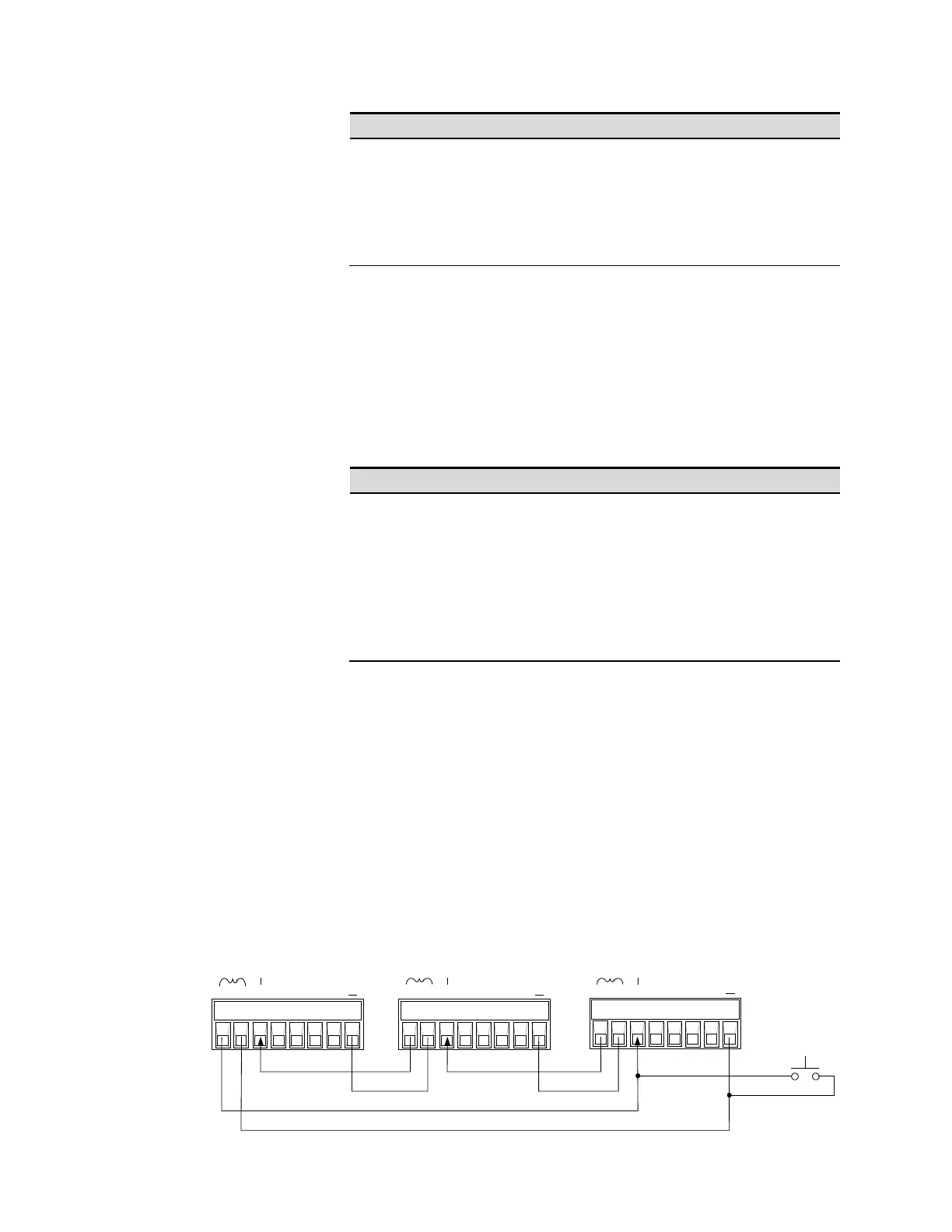
Fault/Inhibit System Protection
The following figure illustrates how you can connect the FLT and INH
pins to coordinate the Fault/Inhibit protection functions across multiple
mainframes.
Panic
switch
INH
Common
INH
Input
FLT
INH
1 2 3 4 5 6 7
I
1 2 3 4 5 6 7
I
1 2 3 4 5 6 7
I
FLT
INH
FLT
INH