2 Installation
38 Series E4360 User’s Guide
If you have questions about connecting outputs in series, contact your
local Keysight Sales and Support Office for details.
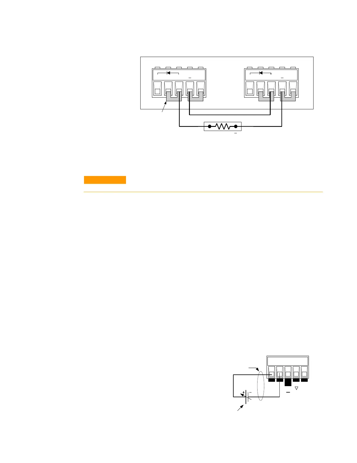
1 Jumpers
installed for
local sensing
+D +s + -s
+
+D +s + -s
output 2 output 1
E4360A
1
R
Load
Analog Current Control
CAUTION
Analog Current Control only applies in Fixed mode operation, and can
program a single output. It cannot be used to program paralleled outputs.
The setup shown below allows an external dc voltage to program the
output channel’s current in Fixed mode. A voltage applied to the
differential current programming input programs the output current.
Note that depending on the polarity of the external source, the external
signal is either added to or subtracted from the programmed current
setting. Output current is internally limited to a maximum of ≈112% of
the output current rating. If you want to fully control the output current
through the analog input, you must first set the output current to zero. A
voltage of 0 - 4 volts programs the output current from zero to the rated
output current.
For proper operation, the maximum common-mode voltage between
either the +IP or -IP inputs and the +OUT terminal should be kept to less
than ±18 volts. Note also that the input impedance of the analog input is
20 kΩ. If the output impedance of your programming source is not
negligible compared to 20 kΩ, the programmed current will be less than
expected.
Be careful of capacitive coupling from the programming inputs to other
lines wired to the analog connector. Such coupling can cause output
oscillations and noise. You can minimize coupling by bundling the +IP
and -IP lines and keeping them separated from other wires. Twisting
these lines together is also recommended.
1 Twist or bundle wire
pairs.
2 A 0 to 4 volt voltage
source programs from zero
to the rated output current