2 Installation
28 Series E4360 User’s Guide
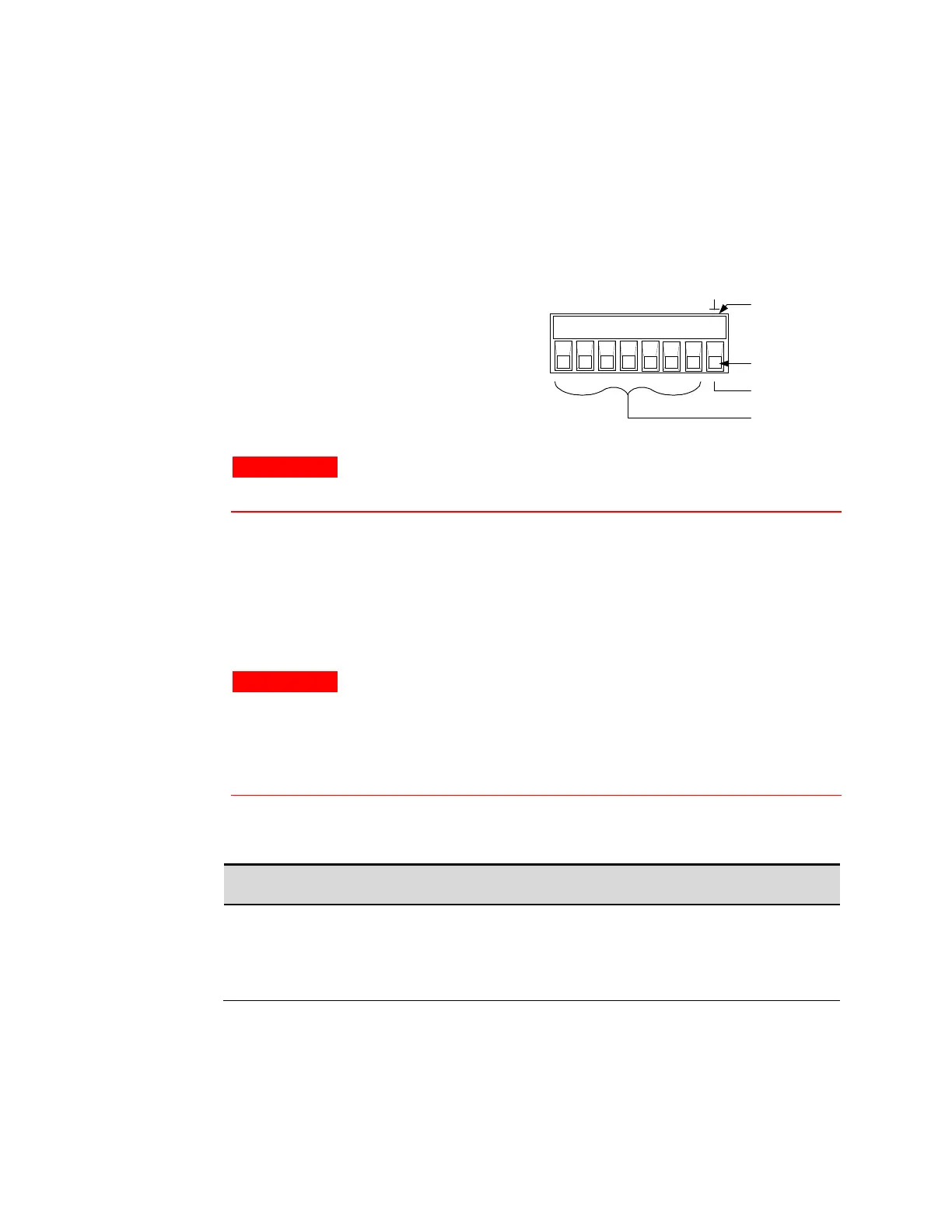
Digital Connector
This connector, which is on the rear panel, is for connecting digital I/O,
fault/inhibit, trigger, or output couple signals. The connector accepts
wires sizes from AWG 16 to AWG 28. Refer to Appendix B for more
information about digital connections.
It is good engineering practice to twist or shield all signal wires to and
from the digital connector.
1 Insert wires
2 Tighten screws
3. Signal common (pin 8)
4. Input/output signals (pins 1–7)
WARNING
The signal common terminal on the digital connector is a low-noise
signal ground for convenience only. IT IS NOT A SAFETY GROUND!
Load Connections
Wire Selection
WARNING
Fire Hazard. Select a wire size large enough to carry short-circuit
current without overheating. To satisfy safety requirements, load
wires must be large enough not to overheat when carrying the
maximum short-circuit current of the unit. If there is more than one
load, then any pair of load wires must be capable of safely carrying
the full-rated current of the output.
The following table lists the characteristics of some common American
Wire Gauge (AWG) sizes of copper wire>
Resistance (at 20 deg. C)
Ω /m Ω /ft