Installation 2
Series E4360 User’s Guide 31
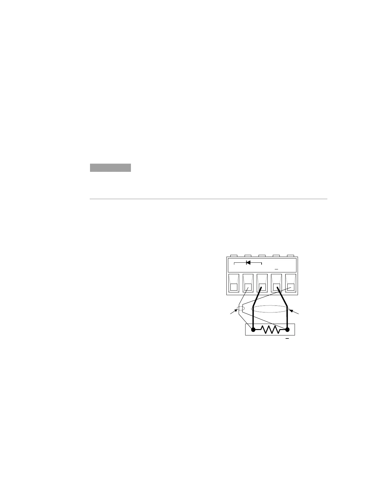
Remote Voltage Sensing
Remote sensing improves the voltage regulation at the load by
monitoring the voltage there instead of at the output terminals. This
allows the unit to automatically compensate for the voltage drop in the
load leads as well as accurately read back the voltage directly at the
load. The maximum allowable load lead voltage drops are:
2 V + (Voc - Vmp).
Fixed mode
2 V
Connect the unit for remote sensing by first removing the local sense
jumpers. Connect the positive side of the load to the +S connector pin
and the negative side of the load to the -S connector pin. Connect the
sense leads carefully so that they do not become open-circuited.
NOTE
If the sense terminals are left unconnected, the voltage at the output
will increase approximately 3 to 5 % over the programmed value. Since
the front panel meter measures the output voltage at the sense
terminals, the voltage reading will not reflect this increase.
Any noise picked up on the sense leads will appear at the output of the
SAS and may adversely affect the load voltage regulation. Be sure to
twist the sense leads to minimize external noise pickup and route them
parallel and close to the load leads. In noisy environments, it may be
necessary to shield the sense leads. Ground the shield only at the SAS.
Do not use the shield as one of the sense conductors.
1 Twist or shield
sense wire pair
2 Twist or bundle
load wire pair
CV Regulation
The Fixed mode voltage load regulation specifications documented in
the Keysight E4360 Modular Solar Array Simulator Specifications Guide
apply at the output terminals of the SAS. When remote sensing, this
specification must be adjusted by adding 3 mV to the voltage load
regulation specification for each 1-volt change in the load leads due to a
change in load current.