Installation 2
Series E4360 User’s Guide 29
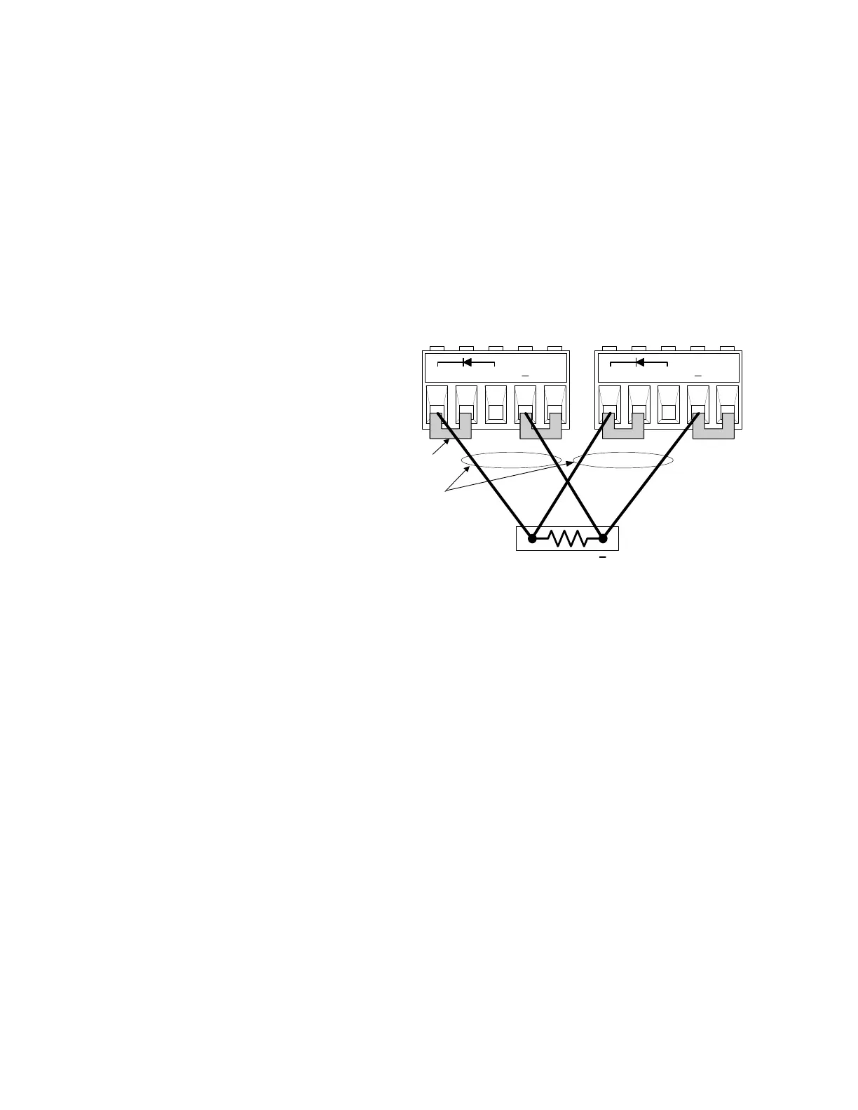
Multiple Outputs
If you are using local sensing and are connecting multiple outputs to one
load, connect each output to the load using separate connecting wires.
Keep each pair of wires as short as possible and twist or bundle them to
reduce lead inductance and noise pickup.
If load considerations require the use of distribution terminals that are
located away from the instrument, connect the output terminals to the
remote distribution terminals by a pair of twisted or bundled wires.
Connect each output to the distribution terminals separately. Remote
voltage sensing is recommended under these circumstances. Sense
either at the remote distribution terminals or, if one load is more
sensitive than the others, directly at the sensitive load.
1 Jumpers installed for
remote sensing
2 Twist or bundle wire pairs
+D +
s + -s
+D +s + -s
2
1
+
R
Load
Reverse-Current Blocking Diode (+D terminal)
The SAS has a built-in reverse-current blocking diode. The cathode
connects to +D; the anode connects to + out. When using this diode,
connect the load to the +D terminal, not to the + output terminal.
In Fixed mode, this diode protects the instrument from reverse currents
that can be generated if a paralleled output or a battery is connected to
an output and its over-voltage protection trips.