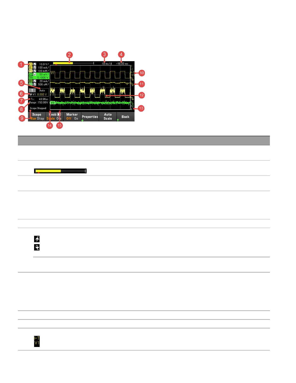
Scope View
Press [Scope/Datalog] key to view the scope. This key toggles between the Scope view and Data Logger view.
Items Description
1 Trace controls Identifies the voltage or current that will be displayed. √ indicates the trace is on. Dashes (----)
indicate the trace is off. Select the trace and press [Enter] to turn it on or off.
2 Data bar The data bar represents all of the logged data. The yellow part indicates the portion of the data that
is visible on the display. The black part represents the data that is not visible.
3 Time/Div Identifies the horizontal time-base setting. This can be adjusted using the Horizontal knob after
pressing Knob Sc.
4 Offset time Indicates the time from the trigger point indicator to the vertical center line of the grid. Negative
values indicate the center line is to the left of the trigger point. Positive values indicate the center
line is to the right of the trigger point. The trigger point can be adjusted using the Horizontal knob
after pressing Knob Ofs.
5 Trigger mode Indicates the trigger mode (Auto, Single, or Triggered).
6 Trigger Source In the figure, the trigger source is a voltage level on input 1.
Up trigger indicates the measurement will be triggered on the up-slope (positive).
Down trigger indicates the measurement will be triggered on the down-slope (negative).
Amplitude If the trigger source is set to a voltage or current level, the amplitude of the trigger level is indicated
below the trigger source. In the figure, the voltage trigger level is set to 0 V.
7 Sample period The indicated scope sample period is based on the horizontal time/div. setting. When the time/div.
setting is less than 2 ms/division, the scope will sample at its fastest rate, depending on the number
of traces selected:
1 trace: 5.12 microseconds
2 traces: 10.24 microseconds
8 Range Range indicates the measurement range setting of the selected trace.
9 Scope status Indicates whether the scope is Running, Stopped, or Waiting for a trigger.
10 Trigger level Shows the location of the voltage or current trigger level and input. In this example, the voltage trig-
ger level of input 1 is shown. The trigger source and amplitude are shown at the left corner of the dis-
play.
118
Keysight EL30000 Series User's Guide