156 Keysight CXG, EXG, and MXG X-Series Signal Generators Service Guide
Troubleshooting
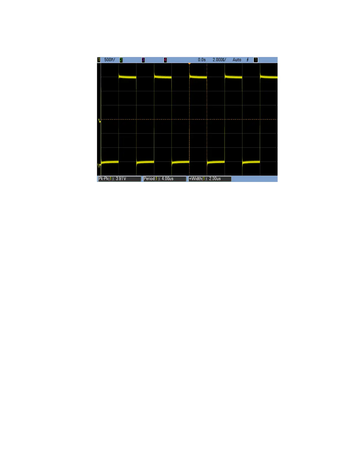
Pulse Modulation Issues (Option UNW)
Figure 6-11 Pulse Modulation Drive Signal – A7A1 U77 Pin 2
12.If either no signal is seen on the oscilloscope, the level is less than 3.2
Vpp, the period is not 4 µs, or the pulse width is not 2 µs, replace the A3
RF assembly.
If the measured voltage is greater than or equal to 3.2 Vpp, the period is 4
µs, and the pulse width is 2 µs, replace the A7 Micro Deck assembly.
 Loading...


