172 Keysight CXG, EXG, and MXG X-Series Signal Generators Service Guide
Power Supply
Troubleshooting
Power Supply Status Quick-Check
For a quick check of the status of all the DC voltages refer to Table 8-2 and
Figure 8-2 for a visual check of the supply voltages with the use of LEDs on the
A3 RF assembly.
While the rest of the voltages will not be on until the instrument is turned on,
the +5 VSB should always be on when there is power applied to the rear panel
power connector.
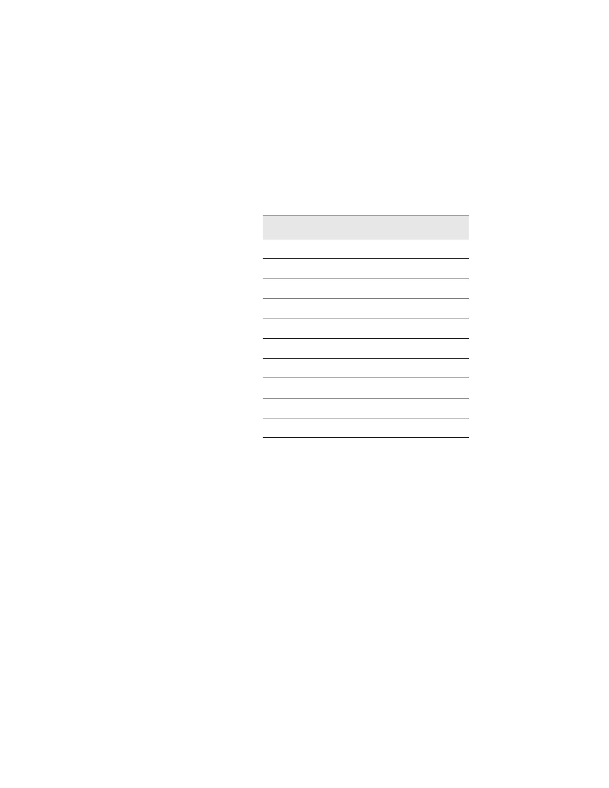
Table 8-2 Power Supply Voltages Versus Status LED
Voltage LED
+32 VA DS305
+15 VA DS308
+9 VA DS307
+5 VA DS306
-7 VA DS309
-15 VA DS310
+12 VD DS314
+5 VD DS312
+3.3 VD DS311
+5 VSB DS313
 Loading...


