Keysight CXG, EXG, and MXG X-Series Signal Generators Service Guide 253
Baseband Generators
A2 Vector BBG Assembly Troubleshooting
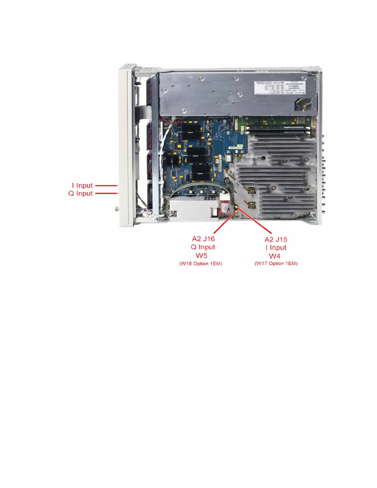
Figure 12-5 I and Q Input Connections – Front Panel
Rear Panel BNC Connectors
There are multiple rear panel BNC connectors on the A2 Vector BBG assembly.
For these to be functional one of the baseband generator options must be
installed in the instrument (653, 655, 656, 657). The I bar and Q bar outputs
also require that option 1EL be installed. The BB TRIG 1, BB TRIG 2, EVENT 1,
and PAT TRIG connectors are all bidirectional. To verify the functionality of
these connectors, follow the procedures below:
I OUT and Q OUT
To verify the functionality of the I and Q outputs use the following procedure,
which will require the use of an oscilloscope:
1. Return the instrument to a known state by pressing Preset.
2. Connect I OUT and Q OUT to channels 1 and 2 of an oscilloscope.
3. Setup the oscilloscope with the following settings:
— All Channels volts per division = 100 mV
— Horizontal scale per division = 500 ns
 Loading...


