254 Keysight CXG, EXG, and MXG X-Series Signal Generators Service Guide
Baseband Generators
A2 Vector BBG Assembly Troubleshooting
4. On the source press Mode, Dual ARB, Select Waveform.
5. Highlight SINE_TEST_WFM and press Select Waveform.
6. Turn the Arb on by pressing Arb On.
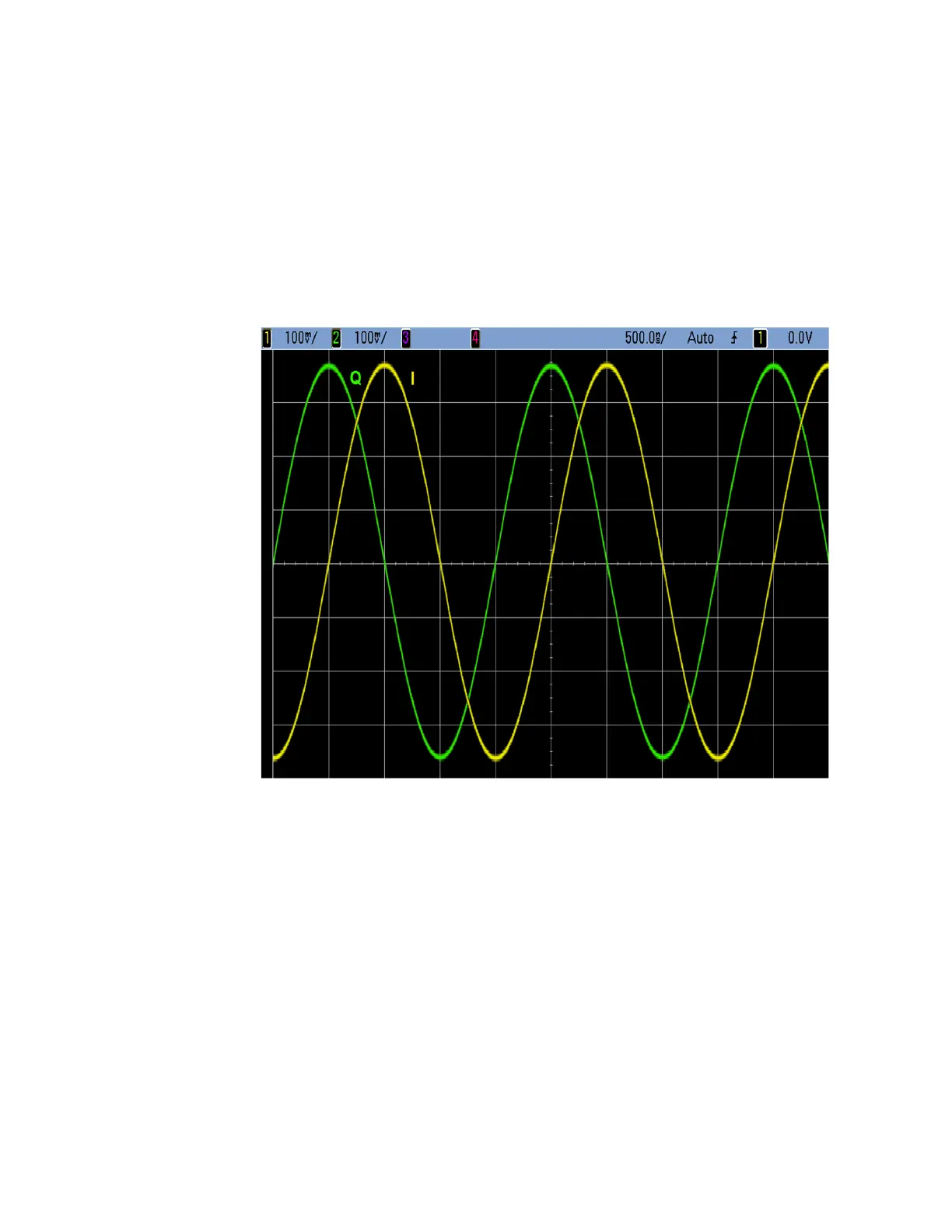
7. The I and Q output signals on the oscilloscope should resemble that seen
in Figure 12-6. If either of the signals does not look like that shown,
replace the A2 Vector BBG assembly.
Figure 12-6 I and Q Outputs
I bar OUT and Q bar OUT
The I bar and Q bar outputs are only active if option 1EL, Differential I/Q
Outputs is installed.
The I bar and Q bar outputs are each 180 degrees out of phase from the I and Q
outputs. To verify the functionality of the I bar and Q bar outputs we will
compare them to the I and Q outputs. This procedure will require the use of an
oscilloscope.
1. Return the instrument to a known state by pressing Preset.
2. Connect the rear panel outputs to the oscilloscope as follows:
— I OUT to Channel 1
— Q OUT to Channel 2
 Loading...


