Keysight CXG, EXG, and MXG X-Series Signal Generators Service Guide 173
Power Supply
Troubleshooting
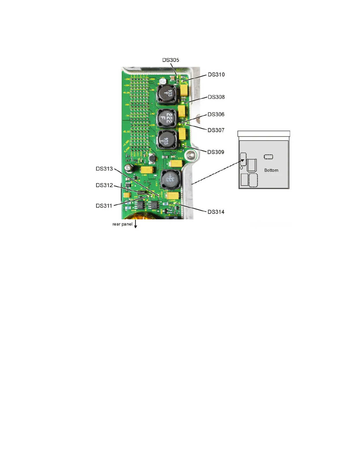
Figure 8-2 Power Supply Voltage LED Locations
If any of the LEDs are not on when they should be, go to the “Measure Voltage
Levels” section in this chapter to verify that the problem is the A1 Power
Supply and not the filtering on the A3 RF assembly.
Measure Voltage Levels
The troubleshooting procedure in this section is designed to be used if any of
the LEDs are not on during the “Power Supply Status Quick-Check”.
Since a power supply LED located on the A3 RF assembly could be off due to a
problem with the filtering of the power supply on that assembly, this procedure
will measure the exact DC voltage levels coming out of the A1 Power Supply
assembly where it connects to the instrument – J10 on the A3 RF assembly.
1. Position the instrument so the A3 RF assembly faces up and the A3 J10
Power Supply connector is easily accessible.
2. Referring to silkscreen on the A3 RF assembly as well as Figure 8-3 and
Table 8-2, measure the DC voltage levels at A3 J10.
If any DC voltages measured are not at the correct level (+/- 10%) replace
the A1 Power Supply.
 Loading...


