168 Appendix E
Caring for Connectors
Mechanical Specifications
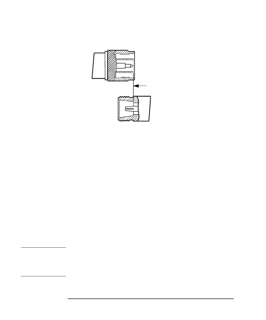
Figure E-5 Type-N connectors
Therefore the mechanical specifications of Type-N connectors give a
maximum protrusion of the female contact fingers in front of the outer
conductor mating plane and a minimum recession of the shoulder of the
male contact pin behind the outer conductor mating plane.
As Type-N connectors wear, the protrusion of the female contact fingers
generally increases, due to wear of the outer conductor mating plane
inside the female connector. This decreases the total center conductor
contact separation and should be monitored carefully.
75 Ohm Type-N Connectors
75Ω Type-N connectors differ from 50Ω Type-N connectors most
significantly in that the center conductor, male contact pin, and female
contact hole are smaller. Therefore, mating a male 50
Ω Type-N
connector with a female 75
Ω Type-N connector will destroy the female
75
Ω connector by spreading the female contact fingers apart
permanently or even breaking them.
NOTE If both 75Ω and 50Ω Type-N connectors are among those on the devices
you are using, identify the 75
Ω Type-N connectors to be sure that they
are never mated with any 50Ω Type-N connectors.
MALE
FEMALE
Outer Conductor
Mating Plane