26 Chapter 2
Test Descriptions
Input VSWR
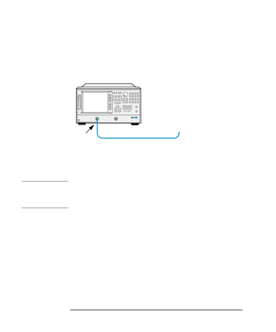
Test Setup
Figure 2-3 Input VSWR: Equipment Connection
Test Procedure
NOTE Throughout the Input VSWR Test Procedure the term ‘the Test Record’
refers to the Input VSWR Test Record detailed in the relevant Appendix
for the model number being tested.
The Input VSWR test requires the following stages:
1. Calibrating the Vector Network Analyzer 1 from 10 MHz to 1.5 GHz
or 3 GHz
2. Measuring VSWR from 10 MHz to 500 MHz
3. Measuring VSWR from 500 MHz to 1000 MHz
4. Measuring VSWR from 1000 MHz to 1500 MHz
5. Measuring VSWR from 1500 MHz to 3000 MHz
6. Calibrating the Vector Network Analyzer 2 from 3 GHz to 6.7 GHz or
26.5 GHz
7. Measuring VSWR from 3000 MHz to 6700 MHz
VECTOR NETWORK
ANALYZER 1
Port 1
Cable 1
Adapter 1
(if Applicable)
Adapter 2
(if Applicable)