64 Keysight P937xA PXIe Service Guide
Removal and Replacement Procedures
Connector Replacement Procedure
5-
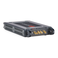
Figure 5-2 Removing the Nut
3. Use the torque wrench with the adapter to remove the nut.
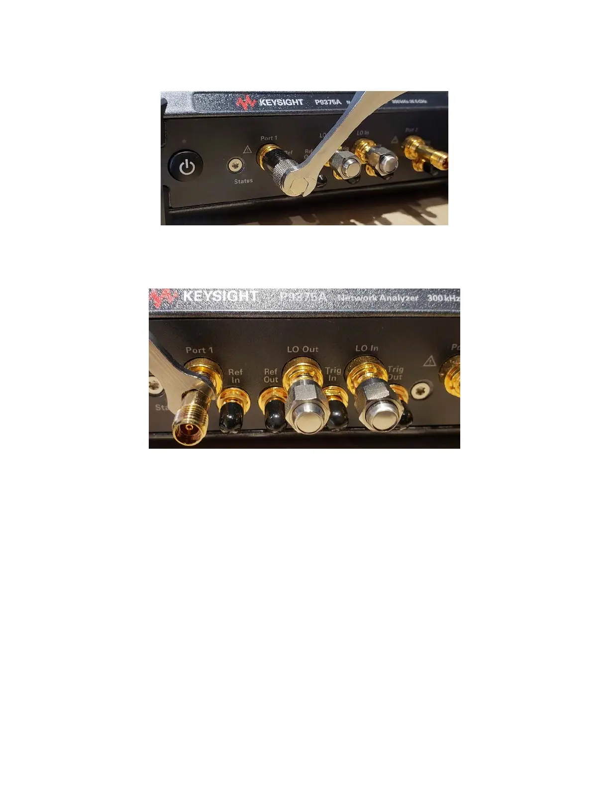
4. Use the torque wrench to remove the connector. Refer to Figure 5-3.
Figure 5-3 Removing the Connector
Replacement Procedure
1. Reverse the order of the removal procedure.
Be careful to install the nut with the slots facing outward.
2. Perform the Op Check to verify the new connectors are functional. Refer to
“The Operator’s Check” on page 33. If it fails, perform the Adjustments
(refer to “Adjustments” on page 48), then repeat the Op Check.
3. For complete assurance that the connectors are meeting all criteria,
perform the following TME Performance Tests. Refer to the TME webpage
at http://cal.software.keysight.com:
— “Source Power Accuracy Test”
— “Source Maximum Power Output Test”
— “Calibration Coefficients Test”
If any of the tests fail, perform the Adjustments (refer to “Adjustments” on
page 48), then repeat the tests.
 Loading...