Keysight P937xA PXIe Service Guide 71
Removal and Replacement Procedures
Module Replacement Procedure
Module Replacement Procedure
Removing and Replacing the A2 Module Assembly
Tools Required
- T-8 TORX driver (set to 6 in-lb)
- T-10 TORX driver (set to 10 in-lb)
- 1/4-inch nut setter bit (set to 6 in-lb)
- 5/16 inch open end torque wrench (set to 8 in lbs)
- ESD grounding wrist strap
Removal Procedure
1. Disconnect the power cord.
2. Turn the instrument over so the bottom feet are facing up.
3. Remove 0515-1227 (x4) screws and old secondary plate P9375-00007.
Save screws and plate for reuse.
4. Remove the front panel. Refer to “Removing and Replacing the A3 Front
Panel Assembly” on page 65.
5. Remove the light pipe from the module. Refer to the Figure 5-5 on page 67.
6. Slide the A2 module out from the chassis.
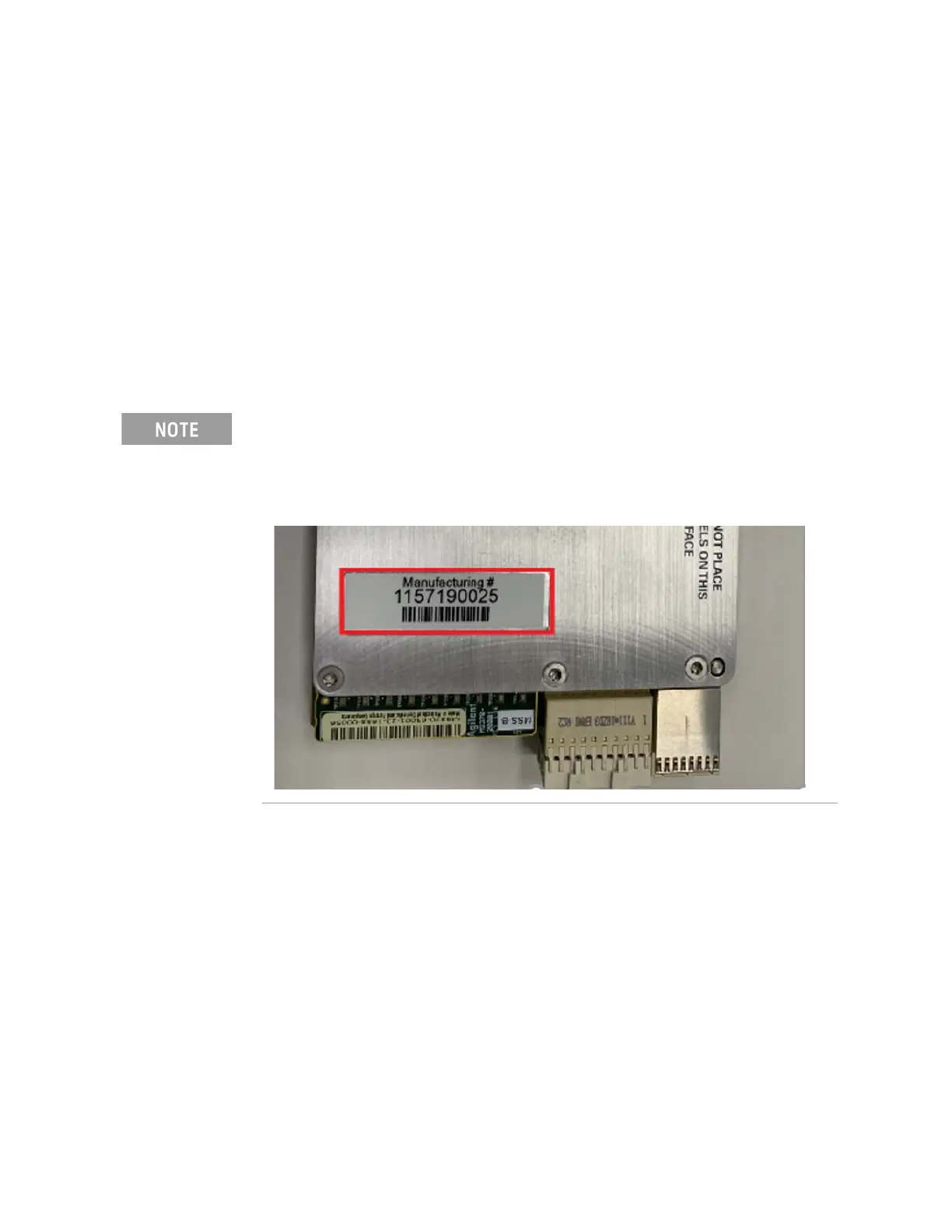
Recording the new module serial numbers.
Each new module is individually serialized, serial numbers are labeled into
the body of each module known as manufacturing ID. Record down the
module serial number as this is needed for the post replacements
procedure.
 Loading...


