Kinco-KS series
PTO0) ,SM77.3 (corresponding to PTO1) , SM97.3 (corresponding to PTO2) and
SM107.3(corresponding to PTO3). The time base can be in either microsecond or millisecond.
All cycle values in the profile table must use same time base, and cannot be modified when the
profile is executing.
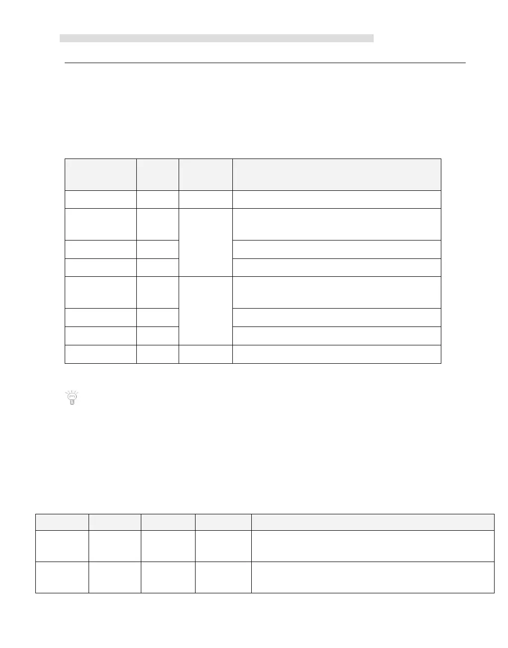
The following table describes the format of the profile table.
The number of segments (1 to 64)
Initial cycle time (2 to 65535 times of the time
base)
Pulse number(1 to 4,294,967,295)
Initial cycle time (2 to 65535 times of the time
base)
Pulse number(1 to 4,294,967,295)
1 All the offsets in this column are relative to the starting position of the profile table.
Notice: the starting position of the profile table must be an odd address in V area, e.g.
VB3001.
Each PTO/PWM generator is provided with some registers in SM area to store its
configurations, as shown in following table.
Whether to update the cycle time: 0 =
No; 1 = Yes
Whether to update pulse width time: :
0=No;1=Yes
 Loading...


