Installation and initial operation
4.3.1. Control system CSP Standard / CSP High Flow
The product is used to control NOX Tiltrotators.
All functions are controlled via proportional valves using joystick handles and can
be executed simultaneously.
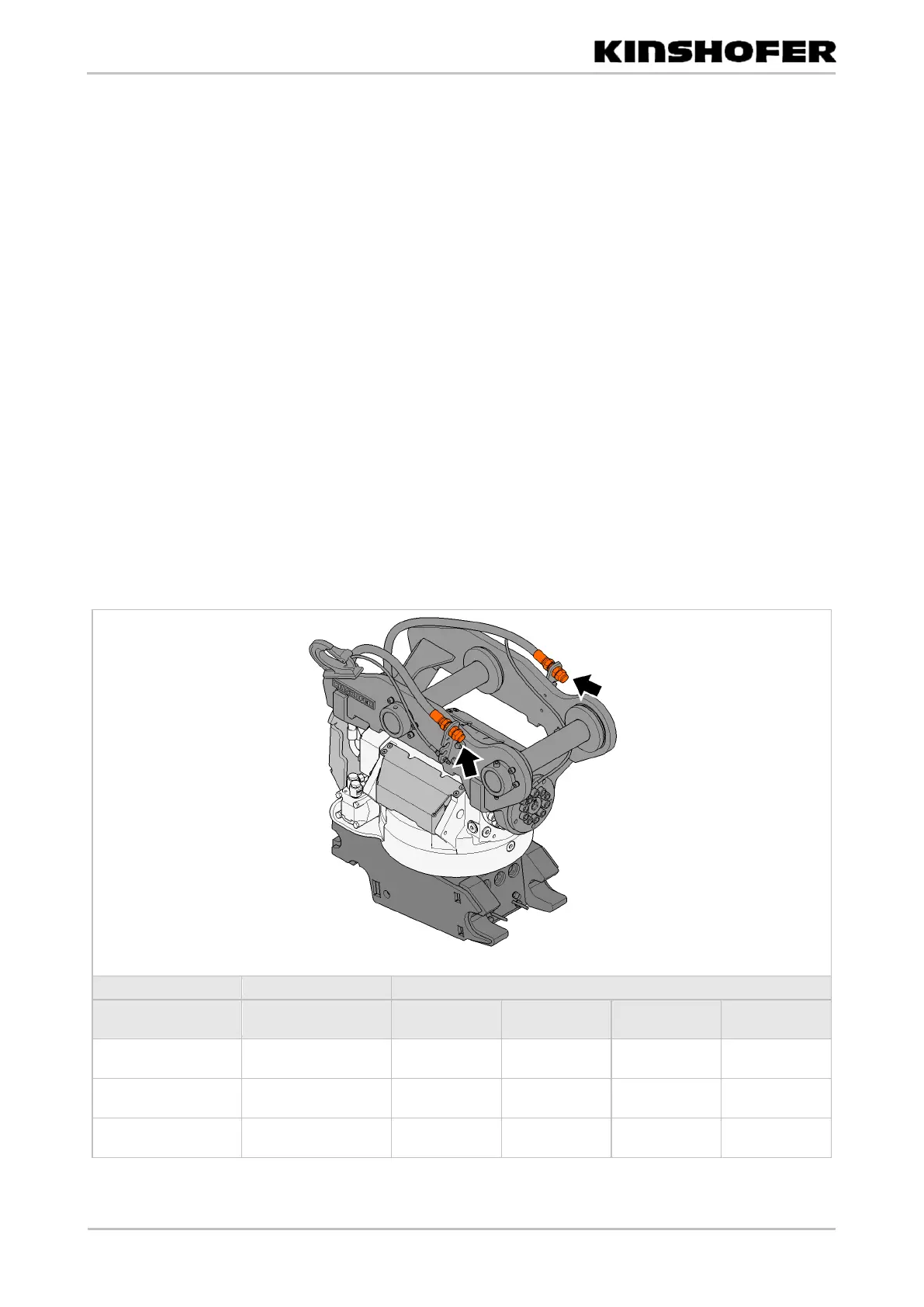
• The hydraulic lines of the attachment are connected with the carrier.
1. First connect the return line (Tank label) to the tank.
2. Connect the supply line (pressure line (Pressure Line label)).
3. Establish the electrical connection.
• Check that the hydraulic oil flows back into the tank without any
backpressure.
• The maximum permissible backpressure is 25 bar.
• Check that the "Hammer" function is selected on the carrier and that the ball
valves are open, especially after a power failure of the on-board battery.
• Completely unscrew the hydraulic quick couplings. This prevents
impermissible backpressure.
• Set the maximum permissible operating pressure and the recommended oil
flow in the table in the chapter Technical data.
1. Test all joystick functions.
2. Correct incorrect settings.
Fig: Hydraulic connections on Tiltrotator
Overflow oil line
(optional)