EasyManua.ls Logo

KINSHOFER TR07 - Controller DF4

Default Icon
80 pages
Print Icon
To Next Page IconTo Next Page
To Previous Page IconTo Previous Page
Loading...
Installation and initial operation
30.03.2020
TR07-TR11-TR14-TR19-TR25
39
4.3.2. Controller DF4
• Control via two double-acting hydraulic circuits, integrated valves for
switching between functions.
• Circuit I controls the rotation function.
• Circuit II controls the tilt function, extra function and the quick coupler, which
cannot be used simultaneously. (Safety circuit integrated for hydraulic quick
coupler)
• Separate overflow oil line (for attachments)
• Electrical swivel (12x 0.5 A) optional
Set the maximum permissible operating pressure and the recommended oil flow
in the table in the chapter Technical data.
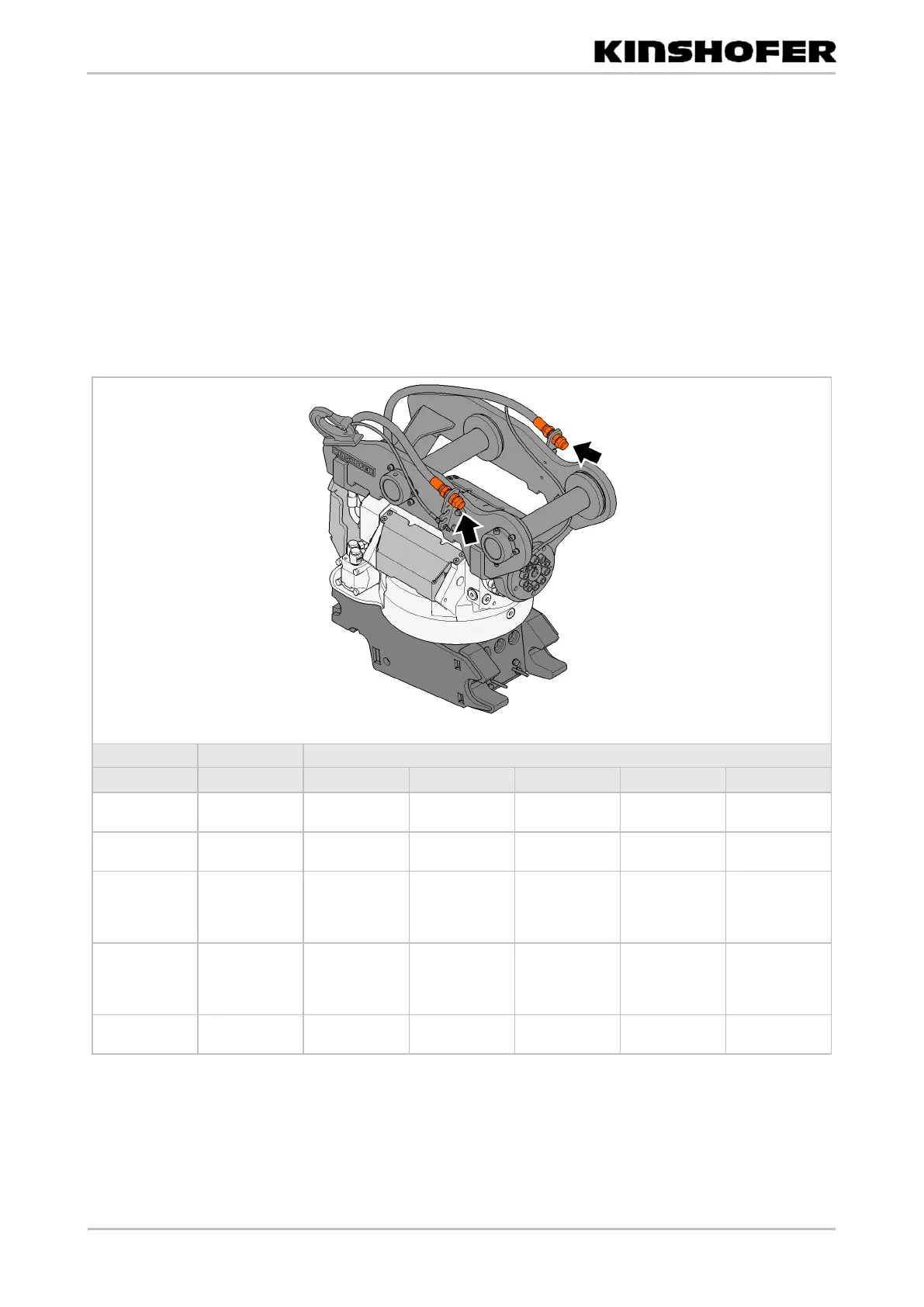
Hydraulic connections on Tiltrotator
Label
Function
Connecting thread
TR07
TR11
TR14
TR19
TR25
Rotation CW
Rotate
clockwise
G 3/8" BSP
G 3/8" BSP
G 3/8" BSP
G 3/8" BSP
G 3/8" BSP
Rotation CCW
Rotate
anti-clockwise
G 3/8" BSP
G 3/8" BSP
G 3/8" BSP
G 3/8" BSP
G 3/8" BSP
tilt LEFT/
EXTRA 1&2
(A)/
coupler
Tilt left/
Extra function
1&2/
Quick coupler
G 3/8" BSP
G 1/2" BSP
G 3/4" BSP
G 3/4" BSP
G 3/4" BSP
tilt RIGHT/
EXTRA 1&2
(B)/
coupler
Tilt right/
Extra function
1&2/
Quick coupler
G 3/8" BSP
G 1/2" BSP
G 3/4" BSP
G 3/4" BSP
G 3/4" BSP
DRAIN LINE
Drain line
(optional)
G 1/4" BSP
G 1/4" BSP
G 3/8" BSP
G 1/2" BSP
G 3/4" BSP
Usage
Checking functions

Table of Contents

Related product manuals