4-5
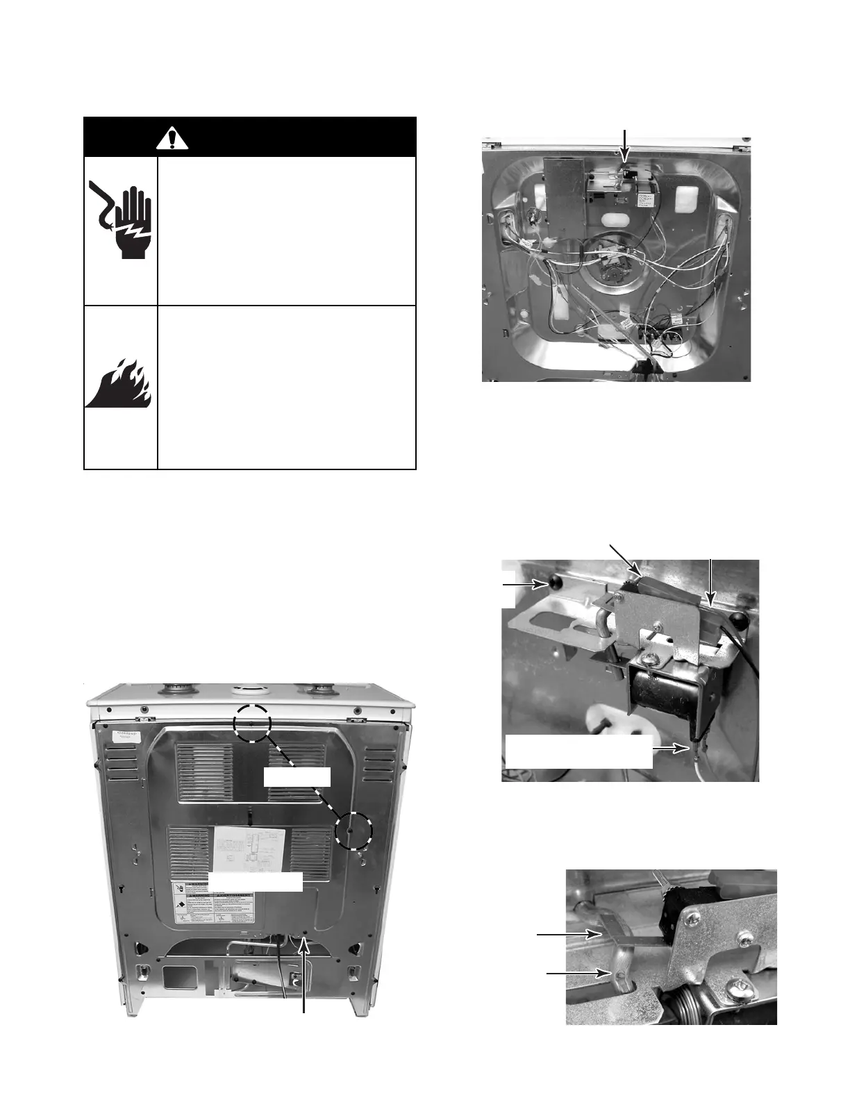
REMOVING THE DOOR LATCH ASSEMBLY
b) Disconnect the 3-wire connector from
the door latch switch terminals.
c) Disconnect the wires from the door
latch solenoid terminals.
d) Remove the two screws from the door
latch assembly and remove it from the
unit.
Rear Panel
2 Screws
Door Latch Assembly
Door Latch Switch
3-Wire Connector
Screw
(1 of 2)
REASSEMBLY NOTE: When you reinstall the
door latch assembly, make sure that the door
latch switch actuator is over the latching rod, as
shown.
Door Latch
Switch Actuator
Latching Rod
Loosen Screw
1. Turn off gas supply and disconnect power
to the range.
2. Pull the range out of its mounting location
so that you can access the rear of the unit.
3. To remove the door latch assembly:
a) Remove the top and side screws from
the rear panel and loosen the bottom
screw, then pull the tabs out of their
slots, and remove the panel.
Door Latch Solenoid
Terminals
WARNING
Electrical Shock Hazard
Disconnect power before
servicing.
Replace all parts and panels
before operating.
Failure to do so can result in
death or electrical shock.
Fire Hazard
Shut off gas supply line valve
before servicing.
Check all gas line connec-
tions and replace all parts
and panels before operating.
Failure to do so can result in
explosion, fire or other injury.