3-1
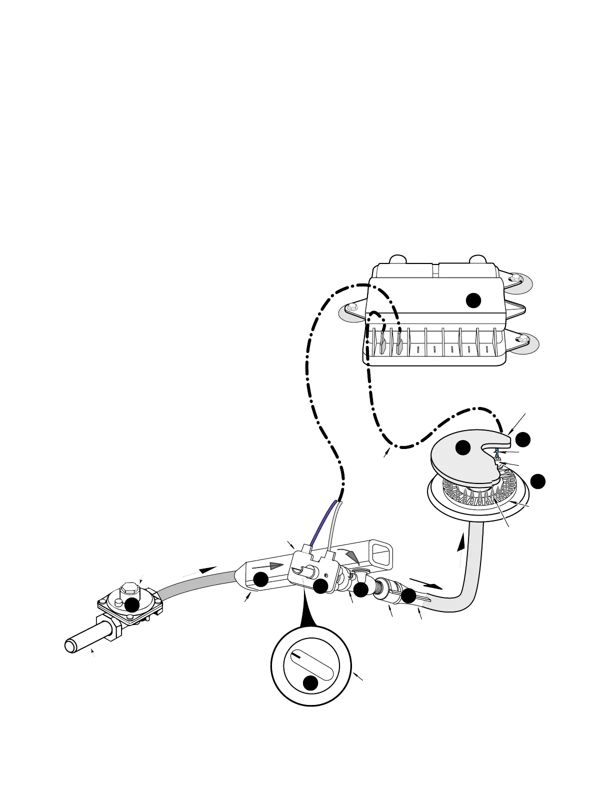
THEORY OF OPERATION
ELECTRONIC IGNITION SYSTEM
SPARK
MODULE
7
GAS DISTRIBUTION
VALVE
GAS INLET
AIR SHUTTER
GAS VALVE
IGNITION SWITCH
VENTURI
BURNER
CONTROL
KNOB
GAS
MANIFOLD
SPARK
IGNITOR
BURNER CAP
TO SPARK
IGNITOR
SPARK
BURNER
BURNER FLAME
GAS FLOW
120 VAC
LINE VOLTAGE
GAS FLOW
HIGH VOLTAGE
PULSES
OFF
LITE
4
9
8
10
2
5
6
1
3
SEALED BURNER
When a main burner control knob q is turned
to the “lite” position, the gas valve r opens,
and gas flows through the gas distribution
valve s into the manifold t through the open
valve. As gas passes through the valve and its
orifice, it is directed into the venturi u, where it
mixes with primary air to create the proper
mixture necessary for combustion.
At the same time, line voltage is applied through
the ignition switch v, to the spark module w,
which produces high-voltage, low amperage
pulses to all of the spark ignitors x. The pulses
cause a spark y to occur between the spark
ignitor electrode, and the grounded burner
cap z. The gas and air mixture at the burner is
ignited by the spark, and a flame is produced at
each of the top burner ports.