6
External Input
The external input (53) can be assigned to any continuous control by using menu level 5. Any
control that is moved while in menu level 5 will 'map' itself to the external input. This is indicated by
the external input level control (48) flashing. The 'mapping' can be cleared by pressing the third
menu button (14) while in menu level 5. The current External Input level is displayed live in menu
level 5 to enable checking of the external control. The External Level control (48) will then set the
maximum effect that the External input (53) will have on the 'mapped' control. The External Input is a
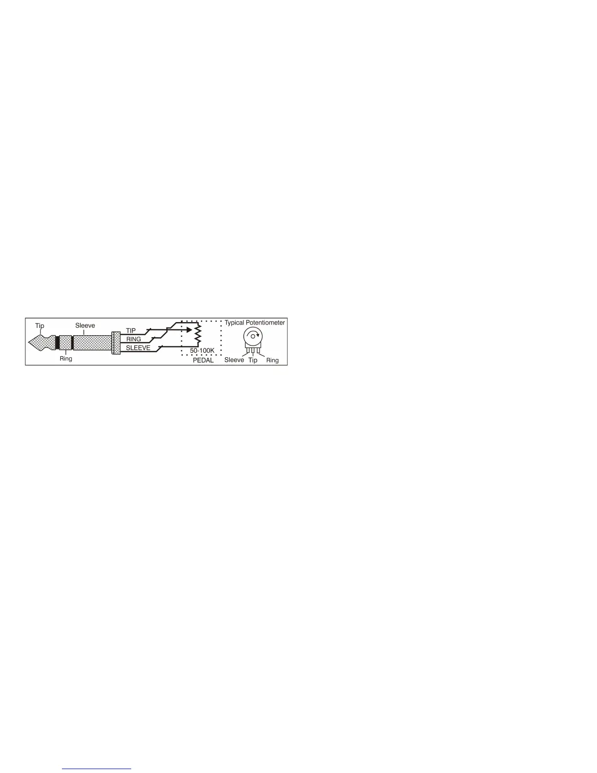
0v to 5v control signal with a 47k input impedance. The tip of the ¼” (6.5mm) External Input socket
is the input, the ring is a 5v supply out and the body is ground. The 5v supply has a 10k pullup and
can source 500µA.
The External Input signal will effect the 'mapped' control in a positive fashion only. For example if the
'mapped' control is at 0% and the External input level control (48) is at 100% then the external input
voltage will cover the full range of the 'mapped' control (0% to 100%). If the 'mapped' control is at
50% and the External input level control is at 50% then the external input voltage will cover the range
50% to 100% of the 'mapped' control. If the 'mapped' control is at 50% and the External input level
control is at 25% then the external input voltage will cover the range 50% to 75% of the 'mapped'
control. If the maximum of the 'mapped' control is exceeded then the level is capped to the control
100% level.
System Reset
The Patch Editor also has a memory erase feature built in which will put the non volatile memory
back to a known state. This is accessed by pressing the XMod Button (24) as the Patch Editor is
powered on. It will set all MIDI channel data to channel 1, LED brightness to 5 and all switches to the
first position.
Power requirements
Power requirements are a single 9vDC supply at 500mA. The polarity is marked on the Patch Editor
and it is protected against reversed power. The required DC plug is 2.5mm ID, 5.5mm OD and a
minimum of 10mm long. It was decided not to include a power unit with the Patch Editor as these
are country specific and easily purchased throughout the world. A universal voltage power pack can
be provided if required but it has a New Zealand plug format and will require adapter plugs for use in
other countries.
The Patch Editor can get warm near the voltage regulator on the back left corner when running on
full brightness with a 12 volt DC supply. If this becomes an issue then either lower the brightness
setting or run the Patch Editor on a 9 volts DC supply. No damage to the Patch Editor will result from
this. 9vDC is the preferred supply.
Program Update
The KiwiTechnics Patch Editor Update Mode is entered by pressing the HPF button while the PE is
powered on. The Update file is then 'played' into the PE using midiOX or similar. The update
progress is displayed on the Display. Once the 'Update Successful' message is displayed the PE
should be repowered.
It is important that there is no midi devices are in the chain between the PC sending the update and
the PE being updated. A direct link is required.
www.kiwitechnics.com Patch Editor v6.0