SECTION 8
ELECTRICAL SYSTEM
p. 8-5
05148408
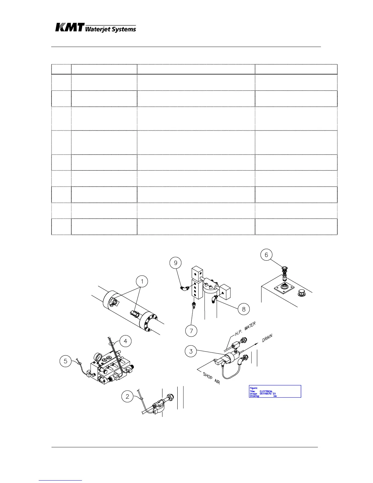
Table 8-2. SENSORS/SOLENOIDS - SLIV
No. FUNCTION COMPONENT DESCRIPTION LOCATION
1 Intensifier shift
sensors
Proximity switches Hydraulic cylinder,
intensifier assy
2 Cutting water
supply
Solenoid shutoff valve, water Bulkhead plumbing
assembly
3 HP water dump
valve
HP shutoff valve, pneumatically-
operated, solenoid valve (pneu)
HP discharge piping,
betw. HP atten. and
bulkhead piping.
4 Intensifier Shift,
A/B Port Shifting
Solenoid- operated, directional
control valve (DCV), hydraulic
pilot- operated spool
Hydr manifold assy,
motor/ pump group
5 HI/LO Pressure
Select
Solenoid shutoff valve, hydr
cartridge style
Hydr manifold assy,
motor/ pump group
6 Low oil level/
temperature
Combination level/ temp switch,
immersed in hyd fluid
Hydraulic reservoir
7 High Booster
Pump Temp
Temperature sensor LP water filter assy,
manifold block
8 Low cutting water
supply pressure
Pressure switch, 30 psig LP water filter assy,
manifold block
9 Low booster
pump pressure
Pressure switch, 60 psig LP water filter assy,
manifold block
 Loading...
